The vector stencils library "Mechanics" contains 29 mechanical symbols.
Use these shapes for drawing mechanics experiment schemes and physical diagrams in the ConceptDraw PRO diagramming and vector drawing software extended with the Physics solution from the Science and Education area of ConceptDraw Solution Park.
www.conceptdraw.com/ solution-park/ science-education-physics
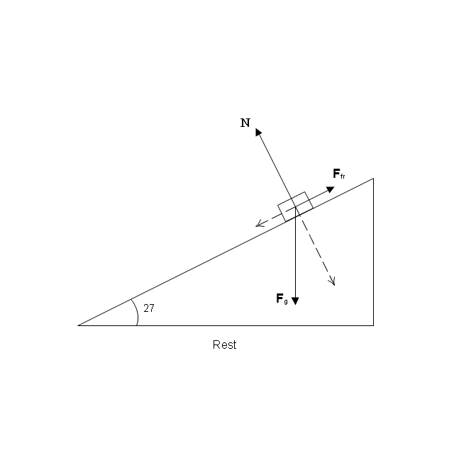
Rest

Co-ordinates
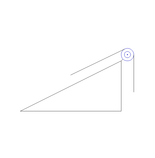
Inclined plane
Block

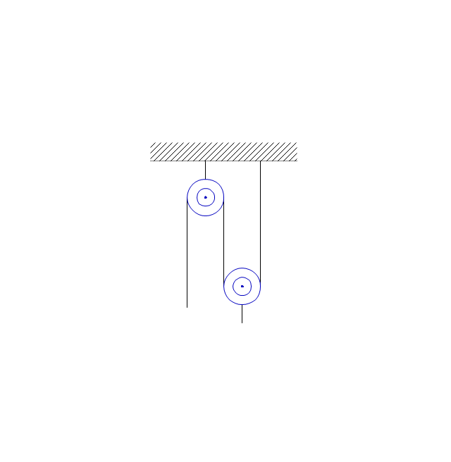
Block System
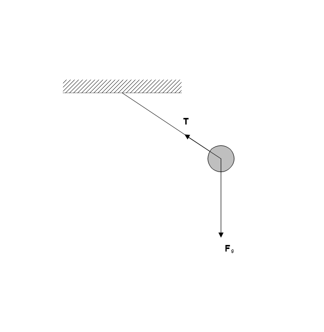
Mathematical pendulum
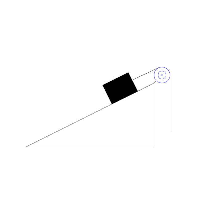
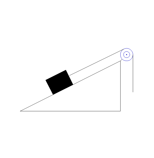
Inclined plane with block
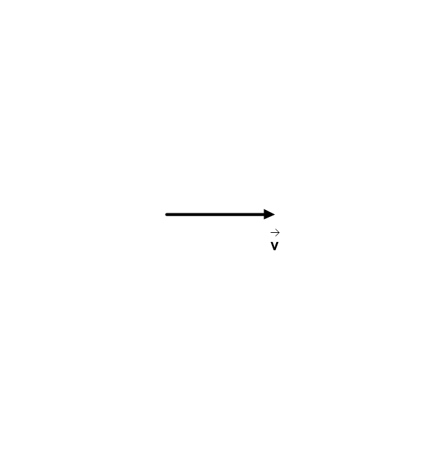
Vector
Parabolic motion path

Parabolic motion path

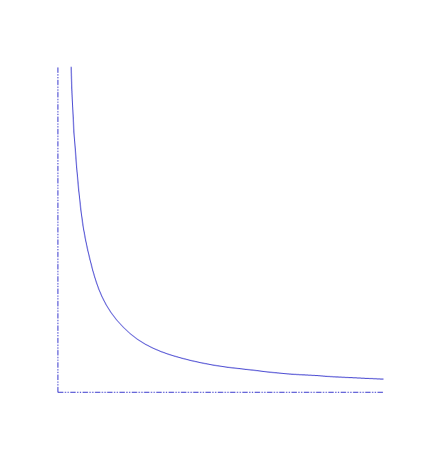
Hyperbolic motion path
Parabolic motion path

Elliptical motion path

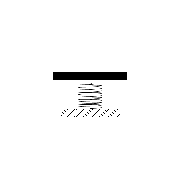
Spring

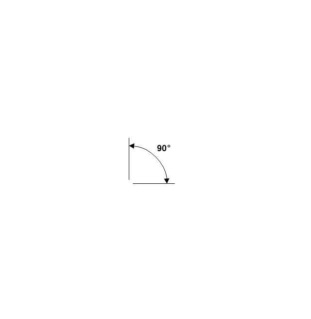
Angle
Linear motion path

Stub Reinforcement

Stick

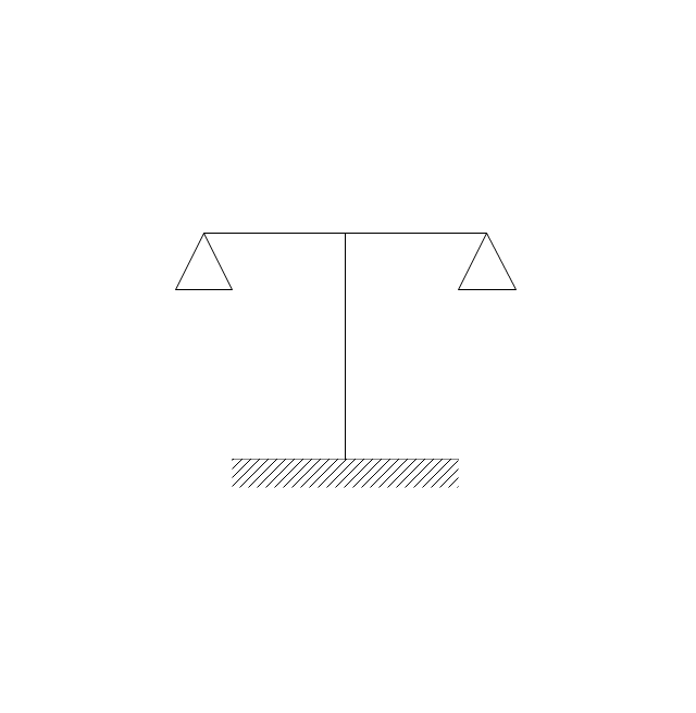
Beam balance
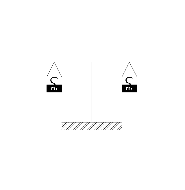
Beam balance 2
Spring Balance
Ball
Weight

Weight, hook

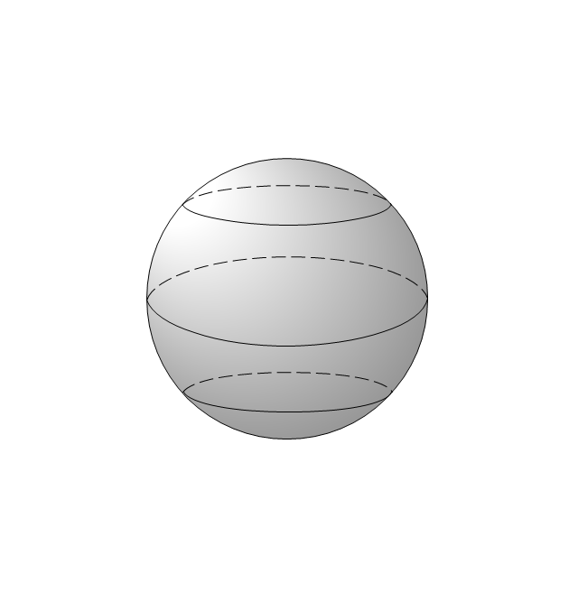
Globe, parallels, meridians

Globe, parallels
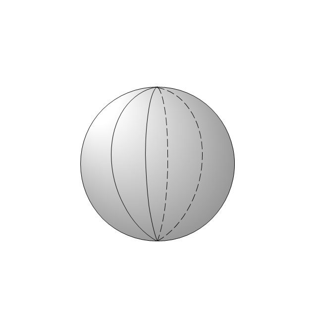
Globe, meridians
Inclined plane with block 2
Inclined plane 2
Mechanical Engineering

 Mechanical Engineering
This solution extends ConceptDraw DIAGRAM.9 mechanical drawing software (or later) with samples of mechanical drawing symbols, templates and libraries of design elements, for help when drafting mechanical engineering drawings, or parts, assembly, pneumatic,
The vector stencils library "Welding" contains 38 welding joint symbols to identify fillets, contours, resistance seams, grooves, surfacing, and backing.
Use it to indicate welding operations on working drawings.
"Welding is a fabrication or sculptural process that joins materials, usually metals or thermoplastics, by causing coalescence. This is often done by melting the workpieces and adding a filler material to form a pool of molten material (the weld pool) that cools to become a strong joint, with pressure sometimes used in conjunction with heat, or by itself, to produce the weld. This is in contrast with soldering and brazing, which involve melting a lower-melting-point material between the workpieces to form a bond between them, without melting the workpieces.
Many different energy sources can be used for welding, including a gas flame, an electric arc, a laser, an electron beam, friction, and ultrasound.
Welds can be geometrically prepared in many different ways. The five basic types of weld joints are the butt joint, lap joint, corner joint, edge joint, and T-joint (a variant of this last is the cruciform joint). Other variations exist as well - for example, double-V preparation joints are characterized by the two pieces of material each tapering to a single center point at one-half their height. Single-U and double-U preparation joints are also fairly common - instead of having straight edges like the single-V and double-V preparation joints, they are curved, forming the shape of a U. Lap joints are also commonly more than two pieces thick - depending on the process used and the thickness of the material, many pieces can be welded together in a lap joint geometry." [Welding. Wikipedia]
The shapes example "Design elements - Welding" was created using the ConceptDraw PRO diagramming and vector drawing software extended with the Mechanical Engineering solution from the Engineering area of ConceptDraw Solution Park.
Welding joint symbols

Network Glossary Definition


- Mechanics - Vector stencils library | Mechanical Engineering ...
- Mechanics - Vector stencils library | Mechanical Engineering | Draw ...
- Mechanics - Vector stencils library | Mechanical Engineering ...
- Mechanical Engineering | Draw A Beam Balance
- Mechanical Engineering | Mechanical Engineering | Diagram Of An ...
- Mechanical Engineering | Mechanical Engineering | Draw Beam ...
- Mechanical Drawing Symbols | Mechanical Engineering ...
- What Is The Symbol For Beams In Industrial Mechanics
- Design elements - Mechanics | Mechanics - Vector stencils library ...
- Math Symbol Balance
- CAD Drawing Software for Making Mechanic Diagram and Electrical ...
- Mechanics - Vector stencils library | Beam Balance Diagram
- CAD Drawing Software for Making Mechanic Diagram and Electrical ...
- Www The Schematic Diagram Of A Beam Balace
- Symbols Of Covcave And Convex
- Mechanical Engineering | CAD Drawing Software for Making ...
- Mathematics | Physics Symbols | Physics Diagrams | Mechanical ...
- Welding symbols | Design elements - Welding | Welding - Vector ...
- Mechanical Drawing Symbols | Mechanical Engineering ...
- Mechanical Drawing Symbols | Mechanical Engineering | CAD ...