 Entity-Relationship Diagram (ERD)
An Entity-Relationship Diagram (ERD) is a visual presentation of entities and relationships. That type of diagrams is often used in the semi-structured or unstructured data in databases and information systems. At first glance ERD is similar to a flowch
HelpDesk
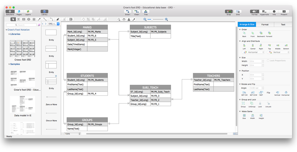
How To Make a Crow's Foot ER Diagram
The Crow's Foot ERD notation is often used in software engineering and database design. The originator of Crow’s Foot notation was Gordon Everest, who offered the idea of how to visually represent the different types of relationships that can exist between objects in an entity relationship diagram (ERD). The Crow’s Foot notation is often used in ER models to how a particular table data can reference data in other tables within a database. The free Crow's Foot Notation solution for ConceptDraw PRO offers a complete vector stencil library containing full standardized symbols of Crow's Foot notation.
 Entity-Relationship Diagram (ERD)
Entity-Relationship Diagram (ERD) solution extends ConceptDraw PRO software with templates, samples and libraries of vector stencils from drawing the ER-diagrams by Chen's and crow’s foot notations.
HelpDesk
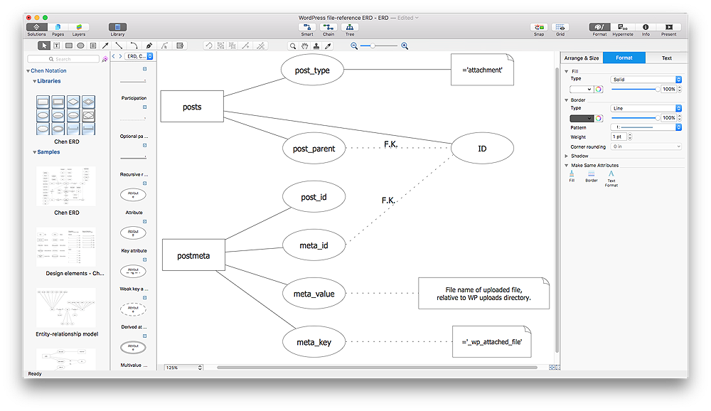
How To Make Chen ER Diagram
The Chen ERD notation model is a popular standard and is widely used worldwide in database and software design. The entity-relationship model proposed by Dr. Chen is constructed using a natural view of how the real world comprises entities and the relationships that exist with these identified entities. It was designed to leverage the advantages of the three entity-data models (network model, relationship model, entity model). The free Chen Notation solution for ConceptDraw PRO provides vector stencil libraries with full standardized Chen notation included."Chen's notation for entity–relationship modeling uses rectangles to represent entity sets, and diamonds to represent relationships appropriate for first-class objects: they can have attributes and relationships of their own. If an entity set participates in a relationship set, they are connected with a line.
Attributes are drawn as ovals and are connected with a line to exactly one entity or relationship set.
Cardinality constraints are expressed as follows:
- a double line indicates a participation constraint, totality or surjectivity: all entities in the entity set must participate in at least one relationship in the relationship set;
- an arrow from entity set to relationship set indicates a key constraint, i.e. injectivity: each entity of the entity set can participate in at most one relationship in the relationship set;
- a thick line indicates both, i.e. bijectivity: each entity in the entity set is involved in exactly one relationship.
- an underlined name of an attribute indicates that it is a key: two different entities or relationships with this attribute always have different values for this attribute.
Attributes are often omitted as they can clutter up a diagram; other diagram techniques often list entity attributes within the rectangles drawn for entity sets." [Entity–relationship model. Wikipedia]
The vector stencils library ERD, Chen's notation contains 13 symbols for drawing entity-relatinship diagrams using the ConceptDraw PRO diagramming and vector drawing software.
The example "Design elements - ER diagram (Chen notation)" is included in the Entity-Relationship Diagram (ERD) solution from the Software Development area of ConceptDraw Solution Park.
- Entity Relationship Diagram Symbols | Basic Flowchart Symbols and ...
- Cycle Diagram With 6 Arrows Black And White
- Entity Relationship Diagram Symbols | ERD Symbols and Meanings ...
- Black And White
- Ethiopian Animal Park Er Diagram
- Simple Black And White User Manual Template Word
- Football Pitch Black And White
- Questions And Answers On Crow Foot Er Diagram
- DroidDia prime | ERD Symbols and Meanings | Data Flow Diagrams ...
- Entity-Relationship Diagram (ERD) | Flowchart design. Flowchart ...
- River Clipart Black And White
- Database Flowchart Symbol In Black And White Color
- Black Line Png
- ABC - Vector stencils library | Abc Lower Case Letters Black And White
- Flowchart design. Flowchart symbols, shapes, stencils and icons ...
- Entity Relationship Diagram Symbols | Basic Flowchart Symbols and ...
- Components of ER Diagram | Entity Relationship Diagram Symbols ...
- White House West Wing - 1st floor | DroidDia prime | Data Flow ...
- Entity Relationship Diagram Examples
- ConceptDraw PRO ER Diagram Tool | Entity Relationship Diagram ...


.png--diagram-flowchart-example.png)