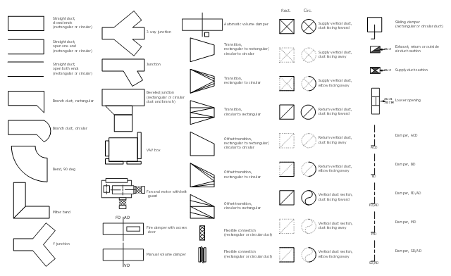
The vector stencil library "HVAC ductwork" contains 63 duct and vent symbols.
Use it for drawing HVAC system diagrams, heating, ventilation, air conditioning, refrigeration, automated building control, and environmental control design floor
plans and equipment layouts.
"Ducts are used in heating, ventilation, and air conditioning (HVAC) to deliver and remove air. These needed airflows include, for example, supply air, return air, and exhaust air. Ducts also deliver, most commonly as part of the supply air, ventilation air. As such, air ducts are one method of ensuring acceptable indoor air quality as well as thermal comfort.
A duct system is often called ductwork. Planning ('laying out'), sizing, optimizing, detailing, and finding the pressure losses through a duct system is called duct design." [Duct (HVAC). Wikipedia]
The vector stencils example "Design elements - HVAC ductwork" is included in HVAC Plans solution from the Building Plans area of ConceptDraw Solution Park.
ConceptDraw DIAGRAM : Able to Leap Tall Buildings in a Single Bound
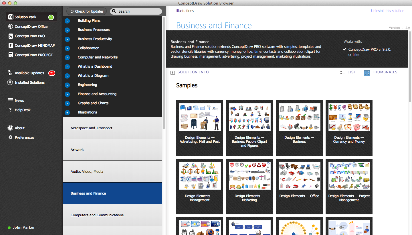
ConceptDraw DIAGRAM is the world’s premier cross-platform business-diagramming tool. Many, who are looking for an alternative to Visio, are pleasantly surprised with how well they can integrate ConceptDraw DIAGRAM into their existing processes. With tens of thousands of template objects, and an easy method for importing vital custom objects from existing Visio documents, ConceptDraw DIAGRAM is a powerful tool for making extremely detailed diagrams, quickly and easily.How To Create Onion Diagram
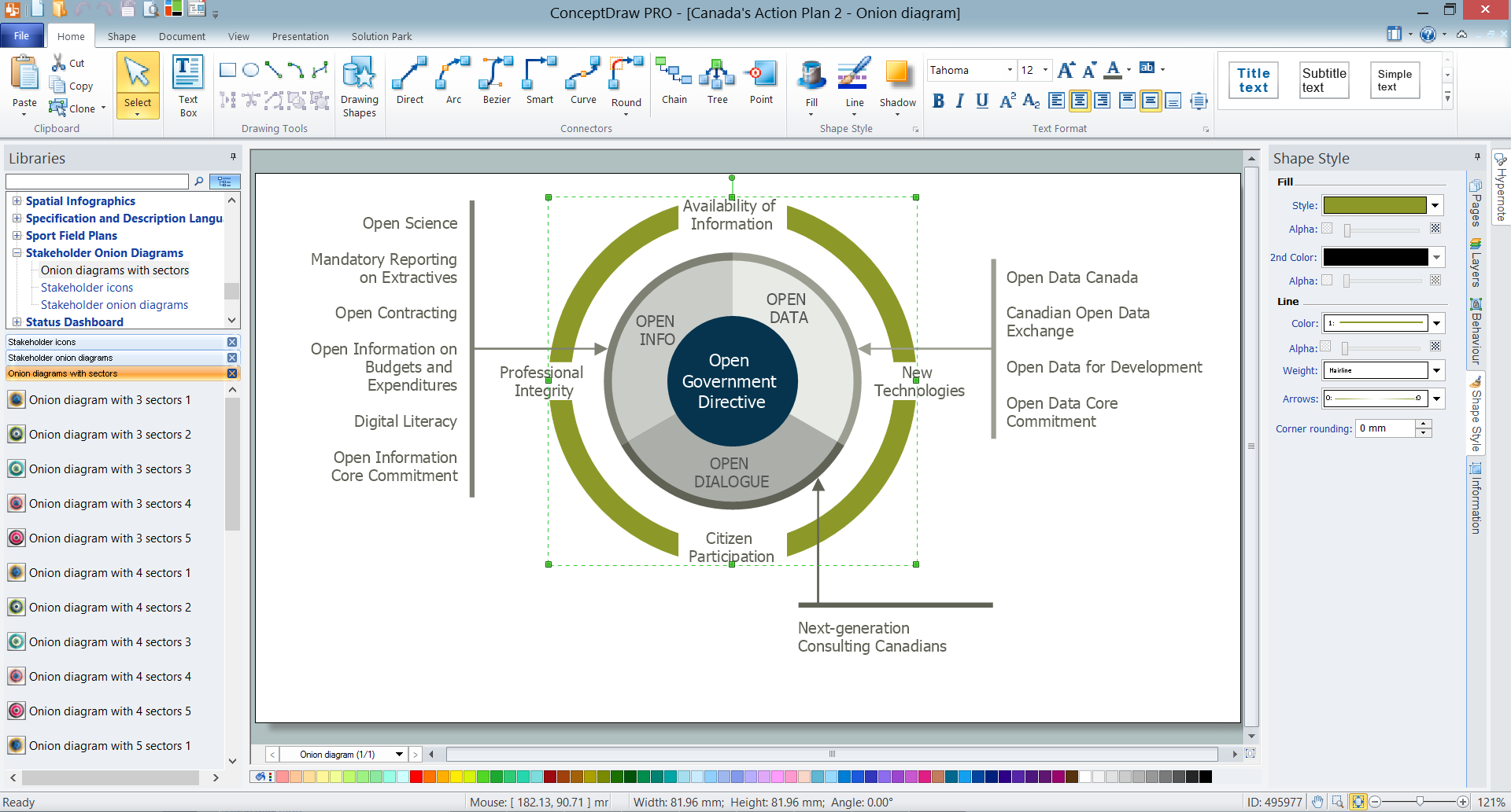
An onion diagram is a kind of chart that shows the dependencies among parts of an organization or process. The chart displays items in concentric circles, where the items in each ring depend on the items in the smaller rings. The Onion Diagram is able to show layers of a complete system in a few circles. But how to create Onion Diagram? Now, it's very easy thanks to the ConceptDraw DIAGRAM diagramming and vector drawing software extended with Stakeholder Onion Diagrams Solution from the Management Area of ConceptDraw Solution Park.Scrum process work items and workflow
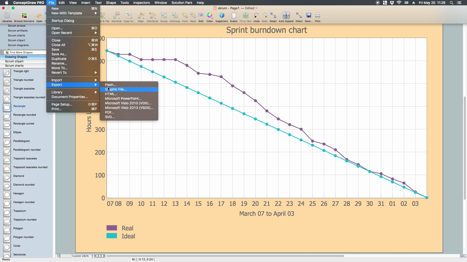
Teams working with Scrum methodology use the product backlog items (PBIs), bug work item types (WITs), reports and dashboards. SCRUM Workflow solution for ConceptDraw DIAGRAM software offers collection of samples, variety of predesigned objects, clipart and graphic elements, a set of Scrum process work items and workflow which are developed for agile teams working using Scrum.
 HVAC Plans
Use HVAC Plans solution to create professional, clear and vivid HVAC-systems design plans, which represent effectively your HVAC marketing plan ideas, develop plans for modern ventilation units, central air heaters, to display the refrigeration systems for automated buildings control, environmental control, and energy systems.
Wireless Network Topology
This sample was created in ConceptDraw DIAGRAM diagramming and vector drawing software using the Computer and Networks solution from Computer and Networks area of ConceptDraw Solution Park. This sample shows the Wireless network topology. Wireless network topology is a logical topology. It shows how the computers connect and interact each other when there is no physical connection, no cables connecting the computers. The computers communicate each other directly, using the wireless devices. Wireless networks can have infrastructure or ad hoc topology.- HVAC Plans
- How to Create a HVAC Plan | Ventilation system layout | House ...
- How to Create a HVAC Plan | Design elements - HVAC ductwork ...
- How to Remove ConceptDraw Products from Mac and PC | Bar ...
- Process Flow Diagram Symbols | Amine treating unit schematic ...
- Process Flow Diagram | Process Flow Diagram Symbols | Chemical ...
- Ductwork layout | HVAC Plans | Design elements - HVAC ductwork ...
- Mechanical Components Symbols
- RCP - HVAC layout | HVAC Plans | How to Create a HVAC Plan ...
- HVAC Plans | Ventilation system layout | HVAC equipment - Vector ...
- Symbols In Doors And Windows In Engineering
- Gate Valve Symbol
- Ductwork layout | HVAC Plans | Design elements - HVAC ductwork ...
- Process Flow Diagram Symbols
- Process Flow Diagram Symbols | Electrical Symbols , Electrical ...
- Design elements - HVAC ductwork
- Ductwork layout | Design elements - HVAC ductwork | HVAC ...
- Electrical Symbols , Electrical Diagram Symbols | Process Flow ...
- Electrical Symbols , Electrical Diagram Symbols | Electrical Symbols ...
- Mechanical Symbol Of A Refrigeration


