HelpDesk
How to Make a UML Diagram in ConceptDraw PRO
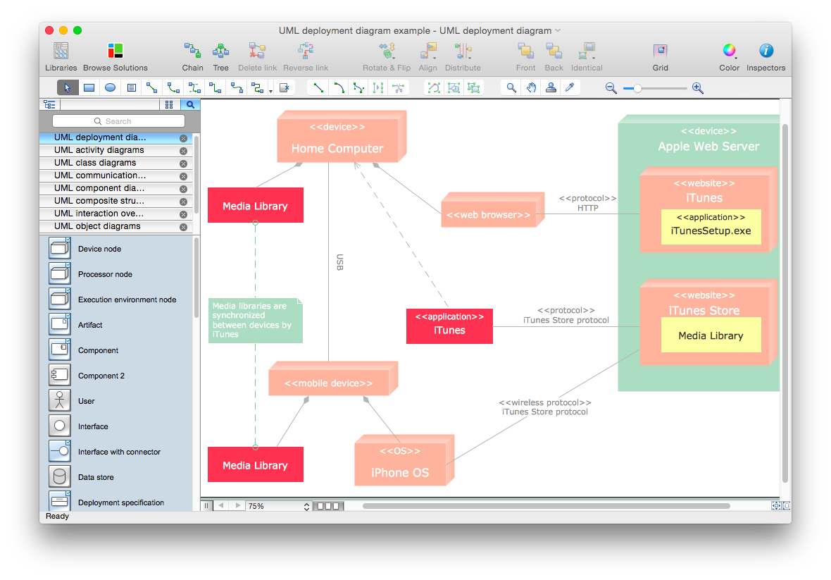
The Unified Modeling Language™(UML) is a standard visual modeling language to document business processes and software architecture. UML uses several types of diagrams including Use Case Diagrams, Class, Package, Component, Composite Structure Diagrams, Deployments, Activities and Interactions. The accepted standard used when modeling a system is known as Unified Modeling Language (UML), a generic set of notations that are used when creating UML diagrams. These notations can visually represent requirements, subsystems, logical and physical elements, and structural and behavioral patterns, that are especially relevant to systems built using an object-oriented style. Using UML during the modeling process has a number of benefits — for one, the entire development team can share information and collaborate using common language, diagrams and software, something that's not possible when using a more task-specific programming language. It allows team members to create system 'blueprin
Data structure diagram with ConceptDraw PRO
Data structure diagram (DSD) is intended for description of conceptual models of data (concepts and connections between them) in the graphic format for more obviousness. Data structure diagram includes entities description, connections between them and obligatory conditions and requirements which connect them. Create Data structure diagram with ConceptDraw PRO.- Organizational Chart Templates | UML composite structure diagram ...
- How to Draw an Organization Chart | Organizational Structure ...
- Process Flowchart | UML Package Diagram . Design Elements ...
- Organizational Structure | How to Draw an Organization Chart | UML ...
- Data structure diagram with ConceptDraw PRO | Diagramming ...
- UML Composite Structure Diagram
- Program Structure Diagrams | Diagramming Software for UML ...
- Organizational Structure | Matrix Organization Structure | Pyramid ...
- Process Flowchart | Flowchart Definition | Organizational Structure ...
- Data structure diagram with ConceptDraw PRO | Organizational ...
- Program Structure Diagrams | PM Easy | Business diagrams & Org ...
- Organizational Structure | How to Draw an Organization Chart ...
- Data structure diagram with ConceptDraw PRO | Active Directory ...
- Organizational Structure | Organizational Structure Total Quality ...
- Data structure diagram with ConceptDraw PRO | Active Directory ...
- UML Class Diagram Example for Transport System | Daigram Of A ...
- Bubble diagrams in Landscape Design with ConceptDraw PRO
- Data structure diagram with ConceptDraw PRO | Diagramming ...
- Pyramid Chart Examples | Business Diagram Software | Rapid UML ...
- Organizational Structure | Process Flowchart | Draw Company ...

