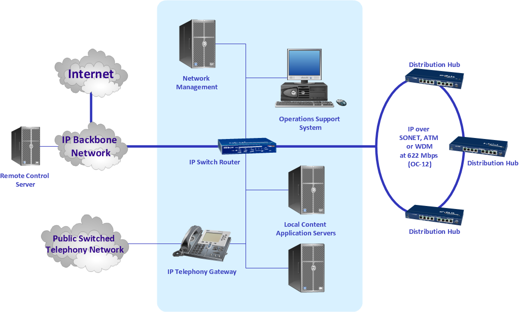
"A cable television headend is a master facility for receiving television signals for processing and distribution over a CATV system. The headend facility is normally unstaffed and surrounded by some type of security fencing and is typically a building or large shed housing electronic equipment used to receive and re-transmit video over the local cable infrastructure. One can also find head ends in power line communication (PLC) substations and Internet communications networks." [Cable television headend. Wikipedia]
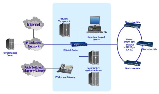
This regional cable head-end diagram example was created using the ConceptDraw PRO diagramming and vector drawing software extended with the Computer and Networks solution from the Computer and Networks area of ConceptDraw Solution Park.
This regional cable head-end diagram example was created using the ConceptDraw PRO diagramming and vector drawing software extended with the Computer and Networks solution from the Computer and Networks area of ConceptDraw Solution Park.
Basic Network Diagram
The Basic Network Diagram is an easy and effective way to design and document a simple network, it lets to represent visually and logically how the different network devices and computer equipment can be installed to meet the main business needs. ConceptDraw DIAGRAM software supplied with Computer Network Diagrams solution from the Computer and Networks area of ConceptDraw Solution Park is a perfect tool for drawing the Basic Computer Network diagrams, designs, schematics, and maps, network architectures, topologies, and layouts. Numerous vector libraries of network symbols, icons and components are incredibly helpful for IT and telecom engineers, stakeholders and end-users when designing Basic Network Diagrams, Common Network Diagrams, Common Network Topologies, 10Base-T Star Network Topologies, Bus Topology Diagrams, Communication Network Diagrams, System Designs, Regional Cable Head-End Diagrams, etc. Collection of predesigned samples and templates included to Computer Network Diagrams solution also greatly extends the capabilities of ConceptDraw DIAGRAM users.
Draw Diagram Software
Entity Relationship Diagram (aka ERD, ER Diagram , E-R Diagram ) is a well-tried Professional ERD drawing and is an essential software engineering method for data visualization. All you need to start draw your diagram is to choose any type of template.Network Diagram Software Backbone Network
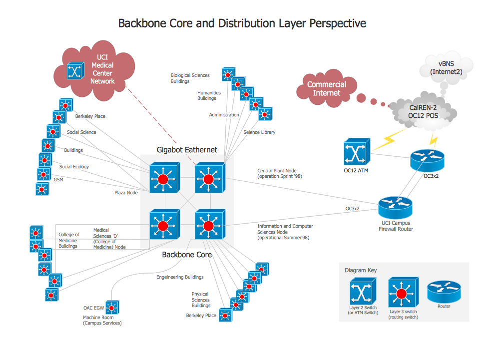
ConceptDraw - Perfect Network Diagramming Software with examples of Backbone Network Diagrams. ConceptDraw Network Diagram is ideal for network engineers and network designers who need to draw Backbone Network diagrams.
Interactive Voice Response Network Diagram
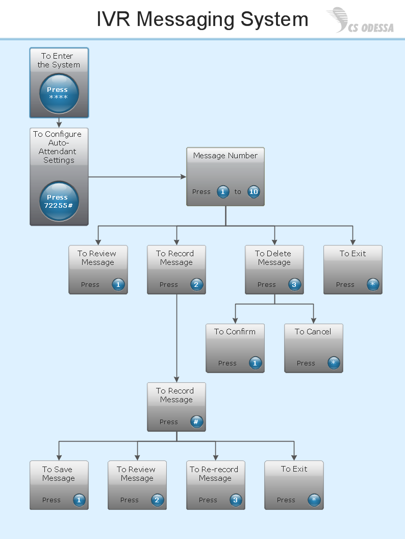
ConceptDraw solution Computer and Networks provides Interactive Voice Response samples, templates and library of 35 vector stencils for drawing the IVR network diagrams. Use ConceptDraw DIAGRAM diagramming and vector drawing software enhanced with solution Computer and Networks to visualize the logical and physical structure of IVR systems for inbound and outbound call centers and voice mail systems.
Design Element: Rack Diagram for Network Diagrams
ConceptDraw DIAGRAM is perfect for software designers and software developers who need to draw Rack Diagrams.
- Basic Network Diagram | ConceptDraw PRO Network Diagram Tool ...
- Regional cable head-end diagram | Bus network topology diagram |
- ConceptDraw PRO Network Diagram Tool | Regional cable head ...
- Network diagrams with ConceptDraw PRO | Regional cable head ...
- Regional cable head-end diagram | Basic Network Diagram ...
- Regional cable head-end diagram | - Conceptdraw.com
- Regional cable head-end diagram | Cisco Network Objects in ...
- Regional cable head-end diagram | - Conceptdraw.com
- Cisco Network Topology | Regional cable head-end diagram ...
- Network Diagram Examples | Bus network topology diagram | Basic ...
- Network diagrams with ConceptDraw PRO | Regional cable head ...
- Network topologies diagram | Design elements - Computer network ...
- Network wiring cable . Computer and Network Examples ...
- Logical network diagram | Diagramming tool - Amazon Web ...
- Design Element: Network Layout for Network Diagrams | Basic ...
- Engineering | Wiring Diagrams with ConceptDraw PRO | Universal ...
- Design elements - Cable TV (CATV) | Cable Network. Computer and ...
- Design elements - Cable TV (CATV) | Cisco Products Additional ...
- ConceptDraw PRO Network Diagram Tool | Network diagrams with ...
- Cable Network. Computer and Network Examples | Network ...


.png)