 Event-driven Process Chain Diagrams
Event-driven Process Chain (EPC) Diagram is a type of flowchart widely used for modeling in business engineering and reengineering, business process improvement, and analysis. EPC method was developed within the Architecture of Integrated Information Systems (ARIS) framework.
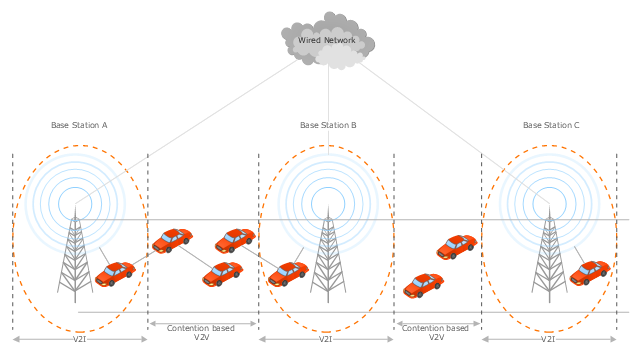
This vehicular network diagram example was drawn on the base of the picture "Inter-Vehicle Communication (IVC) systems" from the website of the Department of Electrical and Computer Engineering, the Ohio State University.
[www2.ece.ohio-state.edu/ ~ekici/ res_ ivc.html]
"Driver assistance systems are meant to support drivers with driving process in order to avoid traffic accidents, speed up the traffic and have a higher control over the traffic in general. There are a lot of systems which give support to the drivers, such as adaptive cruise control, traffic sign recognition, automatic parking, etc. ... the vehicular communication systems ... use the capacity of the vehicles to communicate, not only between them but also with infrastructures. All the information is collected and processed to offer use
ful services. Wireless Sensor Networks (WSN) are widely used in this area. With the incoming upgrades of these networks, they are becoming an attractive solution to give support with the communication mechanisms between vehicles." [mi.fu-berlin.de/ inf/ groups/ ag-tech/ teaching/ 2011_ SS/ S_ 19510b_ Proseminar_ Technische_ Informatik/ daniel-lopez-report.pdf?1346662267]
The vehicular network diagram example "Inter-vehicle communication systems" was created using the ConceptDraw PRO diagramming and vector drawing software extended with the Vehicular Networking solution from the Computer and Networks area of ConceptDraw Solution Park.
Vehicular network diagram
Create Block Diagram

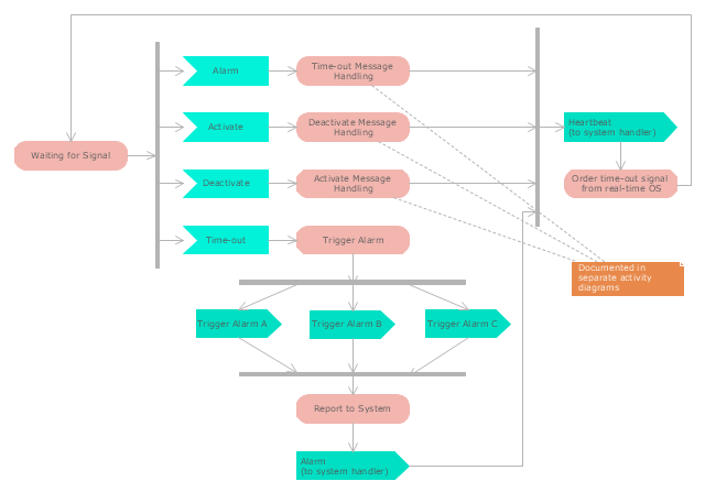
"Alarm triggers.
The individual triggers for a car alarm vary widely, depending on the make and model of the vehicle, and the brand and model of the alarm itself (for aftermarket alarms). Since aftermarket alarms are designed to be universal (i.e., compatible with all 12 volt negative ground electrical systems as opposed to one carmaker's vehicles), these commonly have trigger inputs that the installer/ vehicle owner chooses not to connect, which additionally determines what will set the alarm off." [Car alarm. Wikipedia]
The UML activity diagram example " Alarm trigger processing" was created using the ConceptDraw PRO diagramming and vector drawing software extended with the Rapid UML solution from the Software Development area of ConceptDraw Solution Park.
UML activity diagram
- Car Electrical Wiring Diagram Software Free Download
- Car Wiring Diagram Software Download
- Electrical Drawing Software and Electrical Symbols | Active Directory ...
- Electrical Drawing Software and Electrical Symbols | Car Rewiring ...
- Electrical Drawing Software and Electrical Symbols | Landscape ...
- Event-Driven Process Chain Diagram Software | Process Chart Car ...
- Electrical Drawing Software and Electrical Symbols | Car Wirring ...
- Object Model Diagram Of Car Loans
- Event-Driven Process Chain Diagram Software | UML Use Case ...
- Electrical Drawing Software and Electrical Symbols | Electrical ...
- Car Assembly Process Flow Chart
- Process Flowchart | Event-Driven Process Chain Diagram Software ...
- Activity Diagram For Car Service App
- Electrical Drawing Software and Electrical Symbols | Circuit Diagram ...
- Car In Diagram
- Car Park Drawing Tool
- Event-Driven Process Chain Diagram Software | System Flow Chart ...
- Car Wiring Diagram Software Compbox
- Event-Driven Process Chain Diagram Software | UML Use Case ...