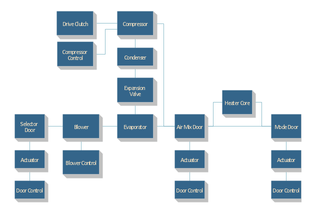
"Automobile air conditioning systems cool the occupants of a vehicle in hot weather, and have come into wide use from the late twentieth century. Air conditioners use significant power; on the other hand the drag of a car with closed windows is less than if the windows are open to cool the occupants evaporatively. There has been much debate on the effect of air conditioning on the fuel efficiency of a vehicle. Factors such as wind resistance, aerodynamics and engine power and weight have to be factored into finding the true variance between using the air conditioning system and not using it when estimating the actual fuel mileage. Other factors on the impact on the engine and an overall engine heat increase can have an impact on the cooling system of the vehicle." [Automobile air conditioning. Wikipedia]
The block diagram example "Automotive HVAC system" was created using the ConceptDraw PRO diagramming and vector drawing software extended with the Block Diagrams solution from the area "What is a Diagram" of ConceptDraw Solution Park.
The block diagram example "Automotive HVAC system" was created using the ConceptDraw PRO diagramming and vector drawing software extended with the Block Diagrams solution from the area "What is a Diagram" of ConceptDraw Solution Park.
Automotive HVAC system
Process Flowchart


 SYSML
SYSML
The SysML solution helps to present diagrams using Systems Modeling Language; a perfect tool for system engineering.
Basic Flowchart Symbols and Meaning


Cisco Products Additional. Cisco icons, shapes, stencils and symbols
")
How To use House Electrical Plan Software


Graphical Symbols to use in EPC diagrams
")
Process Flow Diagram Symbols

Electrical Drawing Software and Electrical Symbols

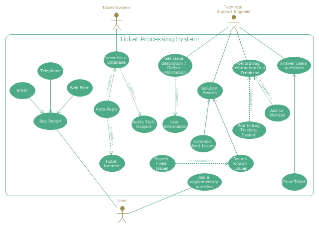
"An example scenario is presented to demonstrate how a common issue tracking system would work:
(1) A customer service technician receives a telephone call, email, or other communication from a customer about a problem. Some applications provide built-in messaging system and automatic error reporting from exception handling blocks.
(2) The technician verifies that the problem is real, and not just perceived. The technician will also ensure that enough information about the problem is obtained from the customer. This information generally includes the environment of the customer, when and how the issue occurs, and all other relevant circumstances.
(3) The technician creates the issue in the system, entering all relevant data, as provided by the customer.
(4) As work is done on that issue, the system is updated with new data by the technician. Any attempt at fixing the problem should be noted in the issue system. Ticket status most likely will be changed from open to pending.
(5) After the issue has been fully addressed, it is marked as resolved in the issue tracking system.
If the problem is not fully resolved, the ticket will be reopened once the technician receives new information from the customer. A Run Book Automation process that implements best practices for these workflows and increases IT personnel effectiveness is becoming very common." [Issue tracking system. Wikipedia]
The UML use case diagram example "Ticket processing system" was created using the ConceptDraw PRO diagramming and vector drawing software extended with the Rapid UML solution from the Software Development area of ConceptDraw Solution Park.
UML use case diagram
Workflow Diagram

Simple & Fast Diagram Software


Cross-Functional Flowchart Basics

Mechanical Drawing Symbols

How to Create a Cross Functional Flow Chart

- Car Engine Block Diagram With Air Conditioning System
- Block diagram - Automotive HVAC system | Cross Functional ...
- Block Diagram Of Car Engine
- Block diagram - Automotive HVAC system | Replacing engine oil ...
- Block diagram - Automotive HVAC system | Cross Functional ...
- Diagram Of Block Engine Of A Car
- Block diagram - Automotive HVAC system | Create Graphs and ...
- Block Diagram For An Automobile System
- Block diagram - Automotive HVAC system | Process Flowchart ...
- Block diagram - Automotive HVAC system | Automobile Air ...
- Block diagram - Automotive HVAC system | Block Diagram Of Car Ac ...
- Block diagram - Automotive HVAC system | Create Block Diagram ...
- Car Air Conditioning System Block Diagram
- Block Diagram Of Car Cooling System
- Block diagram - Automotive HVAC system | Effect Of Hvac In Vehicle ...
- Block diagram - Automotive HVAC system | Functional Block ...
- Car Engine Basic Diagram And Block Diagram
- Block diagram - Automotive HVAC system | Aerospace and ...
- Car Ac System Block Diagram
- Block diagram - Automotive HVAC system | Create Block Diagram ...