Daisy Chain Network Topology
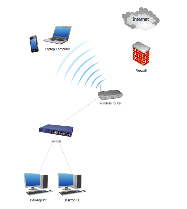
This sample was created in ConceptDraw PRO diagramming and vector drawing software using the Computer and Networks solution from Computer and Networks area of ConceptDraw Solution Park. A Daisy Chain is the simple computer network. It is the easiest way to add more Ethernet devices into the network. In the Daisy Chain network one computer is connected to the next without any intervening devices, thus the message is sent from one computer to the next and then to the next and so on. A Daisy Chain can be linear or ringHow To Create Professional Diagrams
No need for any special drawing skills to create professional looking diagrams outside of your knowledge base. ConceptDraw PRO takes care of the technical side. Use templates, samples and special libraries for your needs.How To use House Electrical Plan Software
How we can conduct the electricity at house correctly without a plan? It is impossible. The House electrical diagram depicts locations of switches, outlets, dimmers and lights, and lets understand how you will connect them. But design of House Electrical Plan looks a complex task at a glance, which requires a lot of tools and special experience. But now all is simple with all-inclusive floor plan software - ConceptDraw PRO. As a house electrical plan software, the ConceptDraw PRO contains libraries with a large range of professional lighting and electrical symbols, ready-to-use electrical plans samples and examples, and built-in templates for creating great-looking Home floor electrical plans. It is a fastest way to draw Electrical circuit diagrams, Electrical wiring and Circuit schematics, Digital circuits, Electrical equipment, House electrical plans, Satellite television, Cable television, Home cinema, Closed-circuit television when are used the tools of Electric and Telecom Plans Solution from ConceptDraw Solution Park. Files created in Visio for Mac app can be easily imported to ConceptDraw PRO. Also you may import stencils and even libraries. Try for free an alternative to Visio that Apple users recommend.
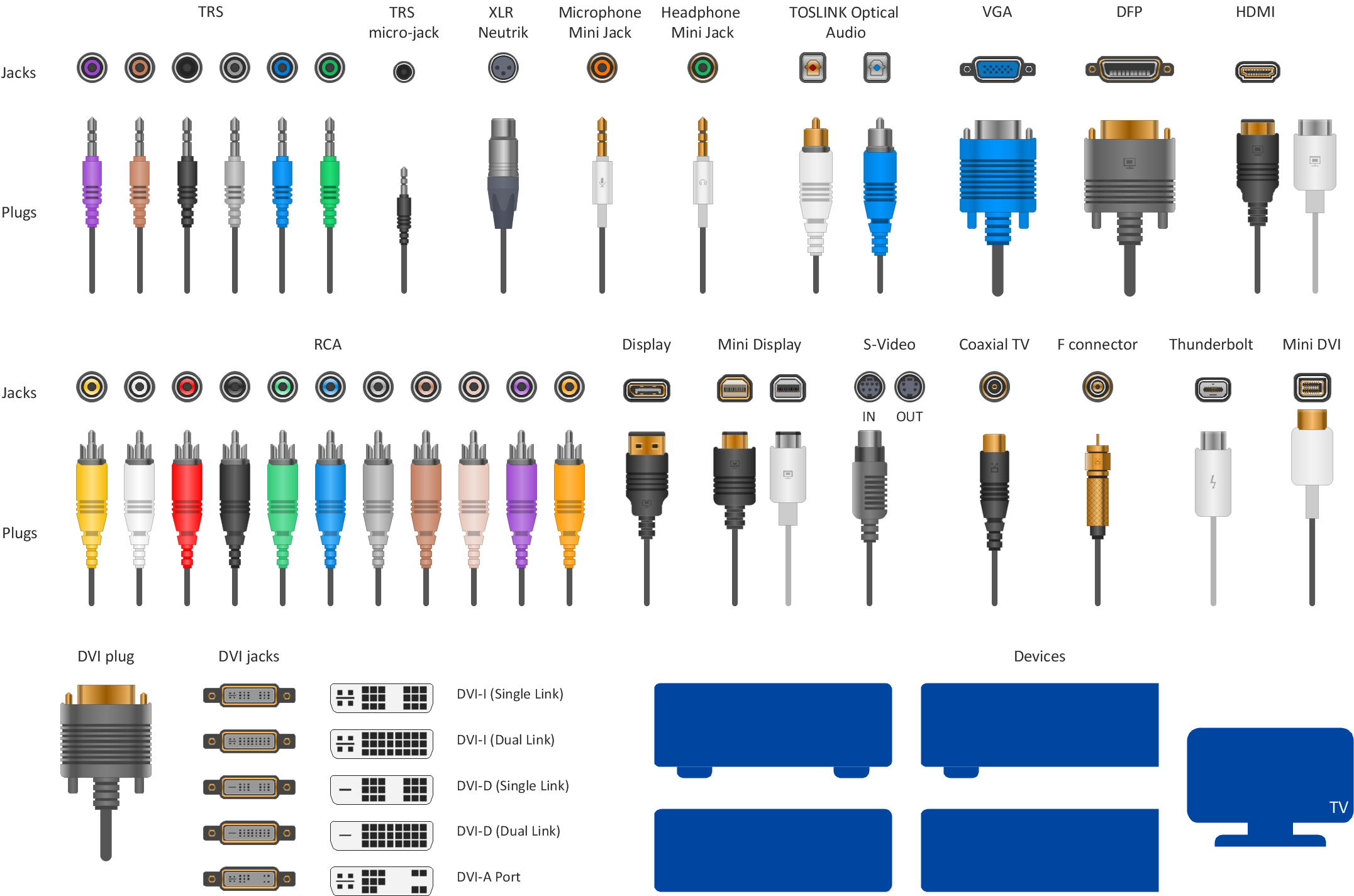
Audio Visual Connectors Types
The Audio & Video Connectors solution contains a set of pre-designed objects, libraries, templates, and samples; allowing quick and easy diagramming of various configurations of audio and video devices.Near field communication (NFC). Computer and Network Examples
Near field communication (NFC) is a wireless communication technology that allows smartphones and other similar devices to establish the radio communication with each other on the short distance around 10 centimeters (4 inches). This example was created in ConceptDraw PRO using the Computer and Networks Area of ConceptDraw Solution Park and shows the Near field communication (NFC) network.
Network Topology Illustration
ConceptDraw PRO is the best software for illustration the network topologies. It's very easy and quickly to design the network topology diagrams of any kinds and complexity in ConceptDraw PRO diagramming and vector drawing software using the Computer and Networks solution from Computer and Networks area of ConceptDraw Solution Park.Digital Communications Network. Computer and Network Examples
The digital communication is a physical transfer of the data over a point-to-point or point-to-multipoint communication channel. Channels can be copper wires, optical fibres, wireless communication channels, etc. The data are realized as electromagnetic signals (radiowave, microwave, electrical voltage, etc.). This example was created in ConceptDraw PRO using the Computer and Networks Area of ConceptDraw Solution Park and shows the Digital Communication Network diagram.
Audio Connectors
Audio connectors are electrical connectors designed and used for audio frequencies. ConceptDraw PRO diagramming and vector drawing software extended with Audio and Video Connectors Solution from the Industrial Engineering Area is the best for drawing various audio schematics with detailed illustration the audio connectors.How to Construct a Fishbone Diagram
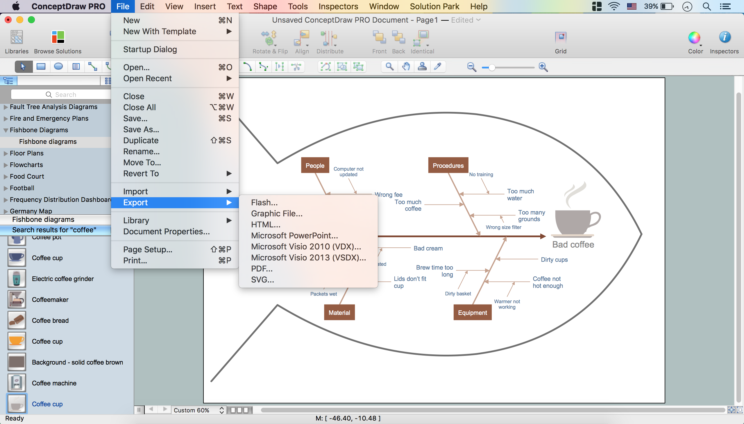
Fishbone, Ishikawa or Cause and Effect diagram helps understand the reasons of completed or potential actions by structuring their causes in smaller categories. Also, one can use it to see how the contributing factors are related to each other. In everyday company routine, a Cause and Effect diagram is helpful with a number of regular activities like brainstorming, project management, and problem solving. How to Construct a Fishbone Diagram? Construction a Fishbone diagram in professional diagramming software ConceptDraw PRO is more easy than you think. Just use the predesigned vector elements from the Fishbone Diagrams library for Fishbone Diagrams solution or one of plenty Fishbone templates and examples, and you will get a Cause and Effect diagram in minutes.- Basic CCTV System Diagram . CCTV Network Diagram Example ...
- How To Create CCTV Network Diagram | CCTV Network Example ...
- Cctv Camera Connection Digram
- Cctv Camera Connection Diagram Pdf
- Cctv Connection Diagram Pdf
- Cctv Wiring Diagram Connection
- Cctv Connection Circuit Diagram
- Dome Camera Cctv Connection Diagram
- CCTV Surveillance System Diagram . CCTV Network Diagram ...
- Circuit Diagram Of Cctv Camera Connection
- How to Create a CCTV Diagram in ConceptDraw PRO | Camera ...
- Cctv Connection Diagram Circuit
- Security Plans | Block Diagram Of Car Cc Tv Connection
- Cctv Connection Diagram Home System
- Cctv Schematic Connection Diagram
- How To Create CCTV Network Diagram | How To Create ...
- How To Create CCTV Network Diagram | How to Create a CCTV ...
- CCTV Surveillance System Diagram . CCTV Network Diagram ...
- Cctv Camera Setup Digram
- Line Diagram Of Cctv Connection


