Local area network (LAN). Computer and Network Examples
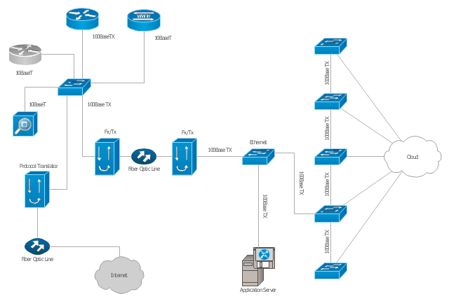
Local Area Network (LAN) is a network which consists of computers and peripheral devices connected each other and to the local domain server, and covers a little territory or small number of buildings, such as home, school, laboratory, office, etc. LAN serves for few hundreds of users. It includes many cables and wires, and demands to design previously a Network diagram. All local area network devices can use the shared printers and disk storage. ConceptDraw DIAGRAM is a perfect network diagramming software with examples of LAN Diagrams, templates and predesigned vector objects. ConceptDraw DIAGRAM is the ideal choice for network engineers and network designers who need to draw fast and easy Local Area Network Diagrams, for IT specialists, developers and other IT professionals which need to visualize the communication schemes of LAN and visually document the LAN's physical structure and arrangement in houses, offices and other buildings. Ready-to-use vector objects from Computer Network Diagrams solution will help you design LAN diagrams in minutes.
"A computer network diagram is a schematic depicting the nodes and connections amongst nodes in a computer network or, more generally, any telecommunications network. ...
Depending on whether the diagram is intended for formal or informal use, certain details may be lacking and must be determined from context. ...
At different scales diagrams may represent various levels of network granularity. At the LAN level, individual nodes may represent individual physical devices, such as hubs or file servers, while at the WAN level, individual nodes may represent entire cities. In addition, when the scope of a diagram crosses the common LAN/ MAN/ WAN boundaries, representative hypothetical devices may be depicted instead of showing all actually existing nodes." [Computer network diagram. Wikipedia]
The Cisco computer network diagram example "Network organization chart" was created using the ConceptDraw PRO diagramming and vector drawing software extended with the Cisco Network Diagrams solution from the Computer and Networks area of ConceptDraw Solution Park.
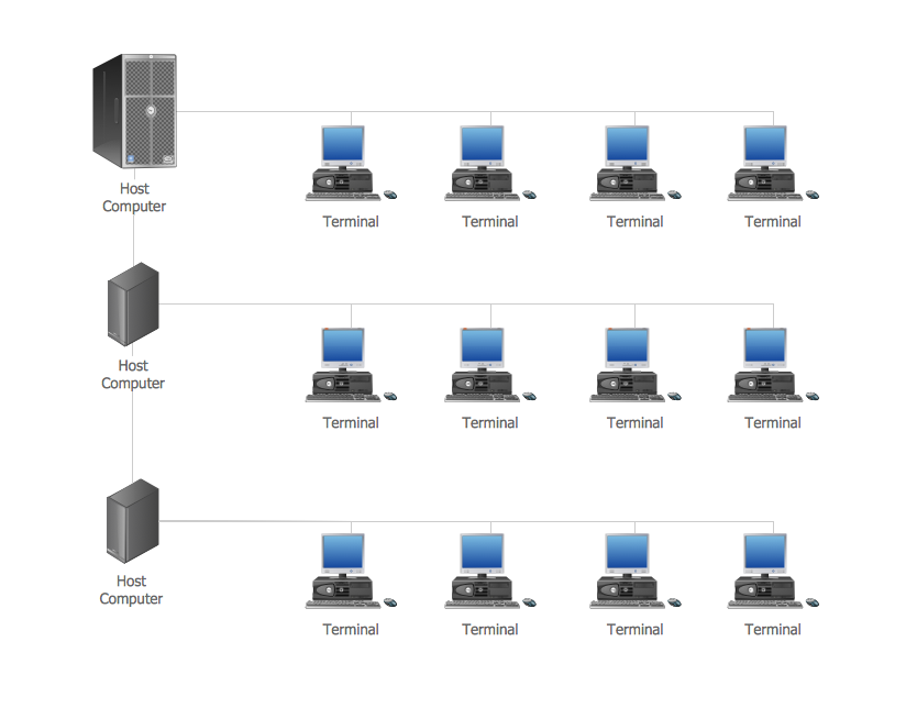
Computer Network. Computer and Network Examples
A Computer Network is a telecommunication network containing the set of nodes (computer network devices, such as computers, phones, servers) and allows them exchange the data using the network links. There are many kinds of computer networks. The primary difference is their size, according to the scale they can be classified as: Local area network (LAN), Metropolitan area network (MAN), Global Area Network (GAN), Wide area network (WAN), Storage area network (SAN), Campus area network (CAN), Personal area network (PAN). Computer networks also differ by connection method according to the used hardware technology (Ethernet, Wireless LAN, Optical fiber, HomePNA, Power line communication), by functional relationships that exist between network elements (Client-server, Active Networking, Peer-to-peer), by network topology (Tree computer network, Bus network, Star network, Ring network, Mesh network, etc.). Solutions of Computer and Networks Area from ConceptDraw Solution Park contain powerful drawing tools for easy designing diagrams for any Computer Network from listed diversity.
AWS
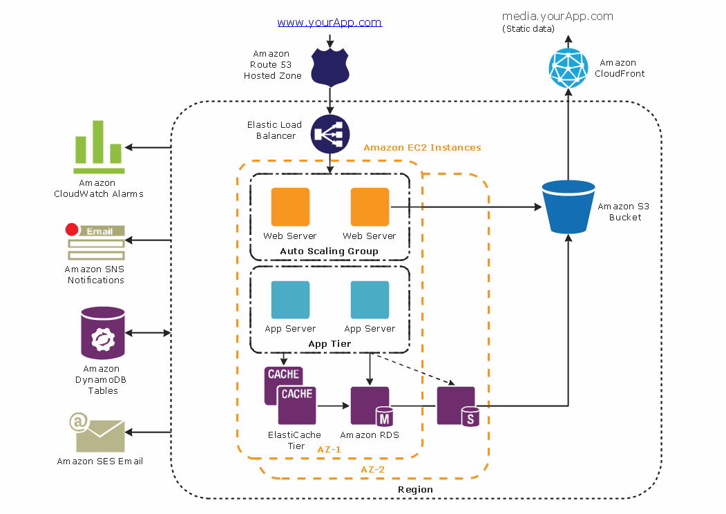
The AWS diagrams are convenient way for explaining the work of Amazon Web Services. ConceptDraw DIAGRAM diagramming and vector drawing software offers the AWS Architecture Diagrams Solution from the Computer and Networks Area for fast and easy creating the AWS diagrams of any complexity.Cisco Network Topology. Cisco icons, shapes, stencils and symbols
Cisco Network Topology represents the arrangement of worldwide recognized and standardized Cisco network symbols, icons, shapes, and stencils which help visualize the schemes of computer networks. Any equipment used in Cisco networks is also named a node and network topology diagram represents the scheme of connection the used nodes. Cisco Network Diagram illustrates how the signals enter on the networked devices and how the data spread within a network from one device to another. These diagrams are useful for engineers while constructing computer networks and working with them. Cisco Network Diagrams solution included to Computer and Networks area of ConceptDraw Solution Park contains quick-start templates, professionally designed samples and examples, and numerous libraries with a lot of predesigned vector design elements, icons, and shapes of Cisco equipment, components, devices, links which provide for ConceptDraw DIAGRAM users a perfect possibility of simple and quick drawing Cisco Network Diagrams and Schematics, Network Designs and Maps of any complexity.- Chart On Networking Lan Wan Man Etc
- Types Of Networks Lan Wan Man All In One Chart With Diagram
- Chart On Lan Wan Man
- Diagrams Of Lan Wan Man Networks
- Show A Chart On Network Basic Show All Lan Man Wan
- Chart On Lan Man Wan
- Chart Of Lan Man And Wan Network
- Chart To Show Lan Wan And Man Netwoks
- Draw A Chart On A Computer Networking Likes Lan Wan Man
- Network Chart On Lan Man Wan
- Physical LAN and WAN diagram
- Diagram Of Lan Wan Man Network
- Graph Of Lan Man Wan
- Explain Lan Wan Man With Digram
- Operating System Lan Wan Man Diagram For It Project
- Lan Wan Man Diagram
- Lan Wan Man Daigram
- Daigrams Of Lan Wan Man
- Diagram The Networks Lan Wan Man
- Flow Chart On Lan Wan Man


