ERD Symbols and Meanings
Entity Relationship Diagram (ERD) is a popular software engineering tool for database modeling and illustration the logical structure of databases, which uses one of two notations - Chen's or Crow’s Foot. Crow's foot notation is effective when used in software engineering, information engineering, structured systems analysis and design. Each of these notations applies its own set of ERD symbols. Crow's foot diagrams use boxes to represent entities and lines between these boxes to show relationships. Varied shapes at the ends of lines depict the cardinality of a given relationship. Chen's ERD notation is more detailed way to represent entities and relationships. ConceptDraw DIAGRAM application enhanced with all-inclusive Entity-Relationship Diagram (ERD) solution allows design professional ER diagrams with Chen's or Crow’s Foot notation on your choice. It contains the full set of ready-to-use standardized ERD symbols and meanings helpful for quickly drawing, collection of predesigned ERD samples, examples and templates. ConceptDraw Pro is a great alternative to Visio for Mac users as it offers more features and can easily handle the most demanding professional needs.
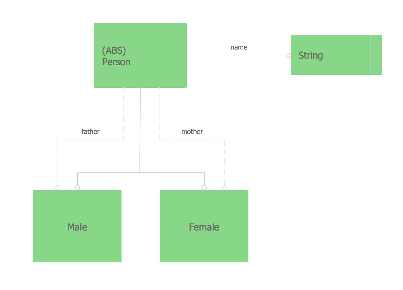
Express-G Diagram
The vector stencils library from the solution Information Model Diagrams contains specific data type symbols of the EXPRESS-G notation such as entity data type symbols, simple data type symbols, enumeration data type symbols, defined data type symbols, select data type symbols and specific attribute symbols for ConceptDraw DIAGRAM diagramming and vector drawing software. The Information Model Diagrams solution is contained in the Software Development area of ConceptDraw Solution Park.SSADM Diagram
The vector stencils library SSADM from the solution Systems engineering contains specific symbols of SSADM diagrams for ConceptDraw DIAGRAM diagramming and vector drawing software. The Systems engineering solution is contained in Software Development area of ConceptDraw Solution Park. The example below illustrates the waterfall model used in SSADM. This model involves 5 stages of developing a product such as requirements specification and its' analysis, design, coding and testing.- ERD Symbols and Meanings | Design Element: Chen for Entity ...
- ERD Symbols and Meanings | Design elements - ER diagram ( Chen ...
- Design elements - ERD (crow's foot notation) | Entity Relationship ...
- Entity Relationship Diagram Symbols
- Design elements - ER diagram ( Chen notation) | Entity Relationship ...
- ERD Symbols and Meanings | Entity Relationship Diagram Symbols ...
- Data Flow Diagram Symbols . DFD Library | Entity Relationship ...
- Entity Relationship Diagram Symbols and Meaning ERD Symbols ...
- ERD Symbols and Meanings | Entity Relationship Diagram Symbols ...
- Entity Relationship Diagram Symbols and Meaning ERD Symbols ...
- Basic Flowchart Symbols and Meaning | Process Flowchart | Design ...
- Entity Relationship Diagram Symbols | ERD Symbols and Meanings ...
- ERD Symbols and Meanings | Entity-Relationship Diagram (ERD ...
- Entity-Relationship Diagram (ERD) | ERD Symbols and Meanings ...
- Design elements - ER diagram ( Chen notation) | Symbol Of Weak ...
- Entity Relationship Diagram Symbols
- ERD Symbols and Meanings | Entity Relationship Diagram Symbols ...
- Design elements - ER diagram ( Chen notation) | Chen's ERD of ...
- Entity-Relationship Diagram (ERD) | ERD Symbols and Meanings ...
- ERD Symbols and Meanings | Entity Relationship Diagram Symbols ...


