This site uses cookies. By continuing to browse the ConceptDraw site you are agreeing to our Use of Site Cookies.

Work Flow Chart

What is a Work Flow Chart? It is a chart which visually displays the step-by-step transferring of data, documents and tasks during the work. ConceptDraw DIAGRAM extended with Workflow Diagrams solution from the Business Processes area of ConceptDraw Solution Park is the best software for drawing the Work Flow Chart of any complexity.

SWOT Analysis Solution - Strategy Tools

The condition and successful development of the company depends on how efficiently it is able to react on different outside influences. Analysis and interrelated consideration of external factors and the company's capabilities allow effectively solve appearing problems. One of the most common methods of evaluation together internal and external factors influencing the company's development is SWOT analysis elaborated for business and industry. It is a necessary element of researches and obligatory preliminary stage at the preparation of strategic and marketing plans of the company. Upon the results of SWOT analysis, we can assess does the company have the internal forces and resources to realize the existing opportunities and resist external threats, and what internal deficiencies require the prompt rectification. ConceptDraw DIAGRAM software enhanced with SWOT Analysis solution offers powerful drawing and strategy tools for effective execution the SWOT and TOWS analysis for your company with a goal of effectively realizing strategic planning and correct decision-making.

Applications

ConceptDraw DIAGRAM is a multipurpose software from ConceptDraw suite intended for diagramming, business and technical drawing, and visual documenting. You can reach a lot of practical benefits from the use of ConceptDraw DIAGRAM. The list of ConceptDraw DIAGRAM applications and versatile possibilities is extremely great. Among them network and system diagramming, business diagramming, Cisco network design, network visualization, software and database design, software development, business flowcharting, data flow design, databases modeling and visualization, business processes modeling, business drawing, technical drawing, GUI prototyping, Organizational charts construction, business processes fixing, web site planning and design, Internet solutions design, information architecture design, UML modeling, ER diagrams design, home and landscape design, and a lot of other applications. ConceptDraw DIAGRAM offers the users a beneficial collaboration, compatibility with MS Visio and many other popular programs, including other products from ConceptDraw suite.

Swim Lanes Flowchart. Flowchart Examples

This sample was created in ConceptDraw DIAGRAM diagramming and vector drawing software using the Cross-Functional Flowcharts solution from the Business Processes area of ConceptDraw Solution Park. This sample shows the Swim Lanes Flowchart of Identification and logging.
Create Swim Lanes Flowchart

Flowchart Components

The ConceptDraw Flowchart component includes a set of samples and templates. This geathered as flowchart maker toolbox which focused on drawing flowcharts of any industry standards.

Create a Flow Chart

Users can start drawing their own flowchart diagrams in fast and simple way with ConceptDraw software.

Porter's Value Chain

ConceptDraw DIAGRAM diagramming and vector drawing software offers you the Matrices Solution from the Marketing Area with extensive drawing tools for creating the Porter's Value Chain diagrams.

Pyramid Diagram

Pyramid chart example is included in the Pyramid Diagrams solution from Marketing area of ConceptDraw Solution Park.

BCG Matrix

The growth–share matrix (BCG Matrix) was created by Bruce D. Henderson for the Boston Consulting Group in 1970 to help corporations to analyze their business units and to help the company allocate resources. How is it easy design the BCG Matrices in ConceptDraw DIAGRAM diagramming and vector drawing software supplied with unique Matrices Solution from the Marketing Area of ConceptDraw Solution Park.

Matrices

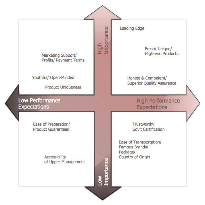
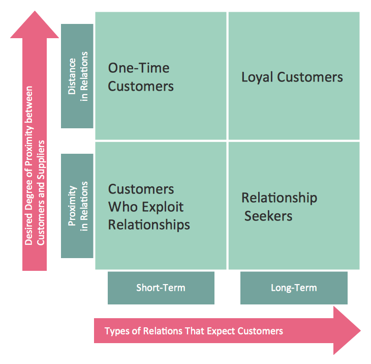
ConceptDraw DIAGRAM extended with Matrices Solution from the Marketing Area of ConceptDraw Solution Park is a powerful software for drawing various types of Marketing Matrices: Ansoff Matrix, BCG Matrix, Deployment Chart, Feature Comparison Chart, Competitive Strategies Matrix, Flow Process Chart, Porter's Value Chain Diagram, Positioning Map, and many others.

Diagramming Software for Design UML Collaboration Diagrams

ConceptDraw helps you to start designing your own UML Collaboration Diagrams with examples and templates.

kanban board, kanban flow, kanban board agile, kanban board example Kanban Board

kanban board, kanban flow, kanban board agile, kanban board example
Kanban Board solution offers an effective way to build the Kanban boards in an electronic view. This solution includes a lot of Kanban Board samples and the great number of predesigned vector design objects of Task Boards, basic symbols, and icons of caution and markers, communication, complete and numbers, emoji and priorities, sticky notes, and team members. Use all advantages of the Kanban boards, Kanban board agile and ConceptDraw’s Kanban Board solution tools, start with any included Kanban Board example and improve your workflow efficiency and personal effectiveness.

How to Create a Pie Chart

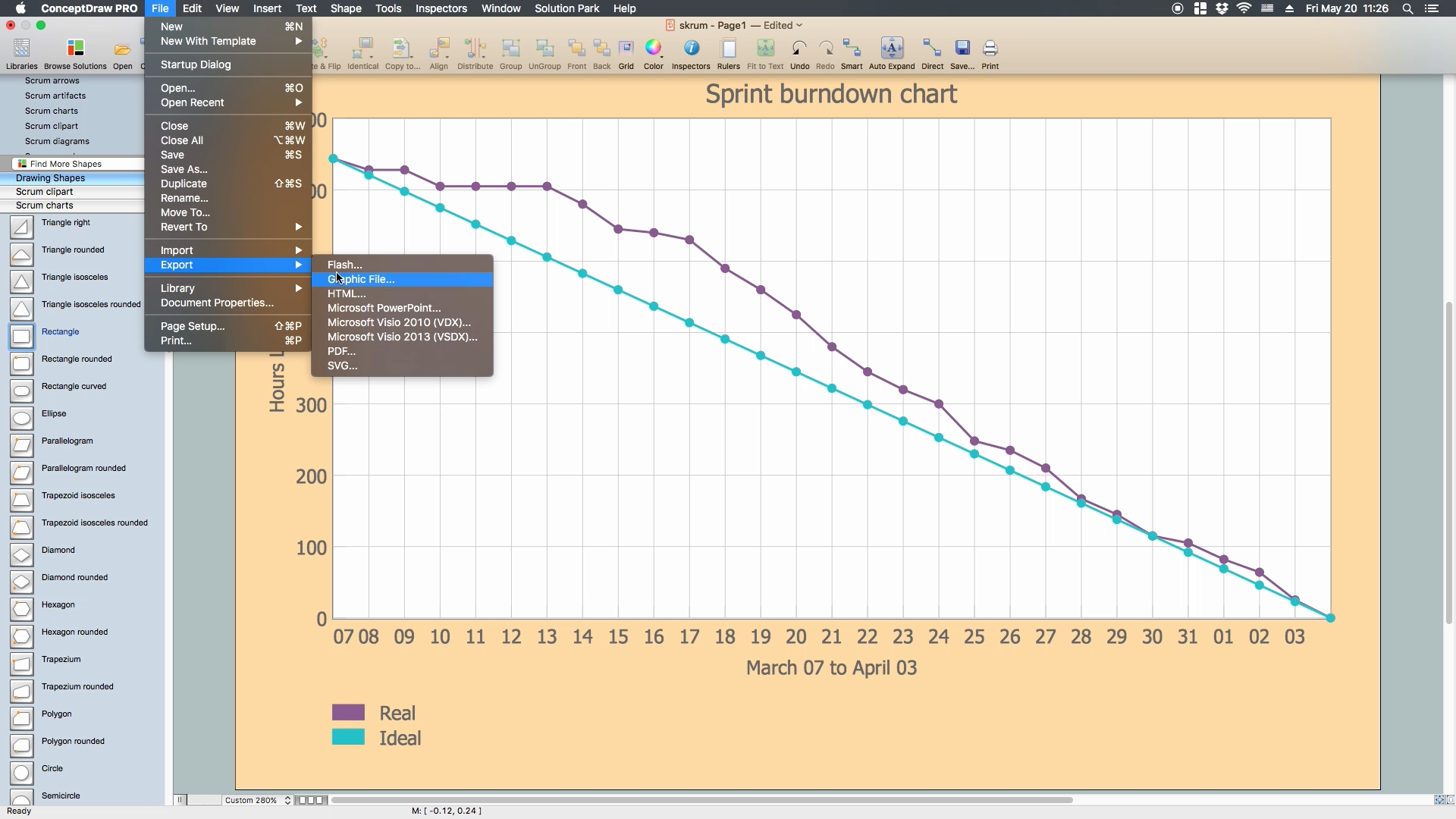
Create a Pie Chart with ConceptDraw software quickly and easily. The simple tutorial helps you learn how to create a pie chart.
This arrow ring diagram sample was created on the base of the figure illustrating the webpage "Grant Life Cycle" from the Georgia College website. "Grant Life Cycle.
Define Opportunity: Funding opportunities can come from anywhere: databases, agency websites, professional publications or colleagues. GC subscribes to the database GRC. Federal grant opportunities can be found through Grants.gov.
Develop Proposal: Once an opportunity has been identified OGSP will do the following:
(1) Review the announcement for application requirements.
(2) Meet with the Principal Investigator (PI) to develop a project management plan.
(3) Work up a draft budget for PI approval.
(4) Complete the sponsor/ required forms and budget justification to be included in the application.
Submit & Negotiate: Applications can only be submitted by GC or the GC Foundation. Once internal approval has been received, designated staff in the appropriate office will submit the application on behalf of the PI and institution. If awarded, the GC or Foundation personnel will review and negotiate acceptable terms and conditions to GC, GC Fdn and/ or USG.
All of these are part of Pre-award services. ...
Award Setup: OGSP will review award documentation and assist all responsible parties with their roles and responsibilities during the grant. OGSP is available through the life of the award to provide support with any non-financial issues.
Manage Subawards: If subawards were identified at application, OGSP will issue the subaward using GC approved forms. If the need for a portion of the work to be completed by an outside entity is noted in the post-award phase, the Grants Compliance Manager will secure agency approval and then issue the subaward. OGSP will monitor the fiscal aspects of the subaward while the PI is responsible for the programmatic compliance.
Execute Project: OGSP continually monitors each grant for compliance with award terms & conditions. As legal representative, OGSP works with the PI and funder to expedite reports and resolve any issues that might arise.
Close Out Project: Once a grant has reached the end of the project period, all funders have requirements for final progress and financial reports. OGSP will work with the PI to make sure the progress report is submitted in a timely fashion and the Business & Finance completes the final invoices or report. The storage of the official project file is the responsibility of OGSP. All information and reports should be copied to the Grant Compliance Manager for inclusion in the official record." [gcsu.edu/ grants/ grantlifecycle.htm]
The arrow ring diagram example "Grant life cycle" was created using the ConceptDraw PRO diagramming and vector drawing software extended with the Target and Circular Diagrams solution from the Marketing area of ConceptDraw Solution Park.
www.conceptdraw.com/ solution-park/ marketing-target-and-circular-diagrams
Arrow ring diagram
Arrow ring diagram, circular arrow diagram, circular motion diagram,
"A project manager is the person responsible for accomplishing the stated project objectives. Key project management responsibilities include creating clear and attainable project objectives, building the project requirements, and managing the constraints of the project management triangle, which are cost, time, scope, and quality.
A project manager is often a client representative and has to determine and implement the exact needs of the client, based on knowledge of the firm they are representing. A project manager is the bridging gap between the production team and client. So he/ she must have a fair knowledge of the industry they are in so that they are capable of understanding and discussing the problems with either party. The ability to adapt to the various internal procedures of the contracting party, and to form close links with the nominated representatives, is essential in ensuring that the key issues of cost, time, quality and above all, client satisfaction, can be realized.
The term and title 'project manager' has come to be used generically to describe anyone given responsibility to complete a project. However, it is more properly used to describe a person with full responsibility and the same level of authority required to complete a project. If a person does not have high levels of both responsibility and authority then they are better described as a project administrator, coordinator, facilitator or expeditor." [Project manager. Wikipedia]
The UML use case diagram example "Project administrator" was created using the ConceptDraw PRO diagramming and vector drawing software extended with the Rapid UML solution from the Software Development area of ConceptDraw Solution Park.
UML use case diagram
UML use case diagram, use case, actor,
The vector stenvils library "Outlets" contains 57 symbols of electrical outlets.
Use these shapes for drawing building interior design, electrical floor plans and layouts of AC power plugs and sockets in the ConceptDraw PRO diagramming and vector drawing software.
The vector stencils library "Outlets" is included in the Electric and Telecom Plans solution from the Building Plans area of ConceptDraw Solution Park.
Single Outlet
Single Outlet, single outlet,
Single Outlet and Switch
Single Outlet and Switch, single outlet, switch,
Emergency Circuit Single Outlet
Emergency Circuit Single Outlet, emergency circuit single outlet,
Duplex Convenience Outlet
Duplex Convenience Outlet, duplex convenience outlet,
Emergency Circuit Duplex Outlet
Emergency Circuit Duplex Outlet, emergency circuit duplex outlet,
Weatherproof Convenience Outlet
Weatherproof Convenience Outlet, weatherproof convenience outlet,
Range Outlet
Range Outlet, range outlet,
Switch and Convenience Outlet
Switch and Convenience Outlet, switch, convenience outlet,
Radio and Convenience Outlet
Radio and Convenience Outlet, radio, convenience outlet,
Radio Outlet
Radio Outlet, radio outlet,
Dedicated Duplex Outlet
Dedicated Duplex Outlet, dedicated duplex outlet,
Duplex Ground Fault Interrupter
Duplex Ground Fault Interrupter, duplex ground fault interrupter,
Split Wired Duplex Outlet
Split Wired Duplex Outlet, split wired, duplex outlet,
240v Outlet
240v Outlet, 240v outlet,
Floor Mounted Outlet
Floor Mounted Outlet, floor mounted, outlet,
Floor Special-purpose Outlet
Floor Special-purpose Outlet, floor special-purpose outlet,
Heavy Duty Outlet
Heavy Duty Outlet, heavy duty outlet,
Heavy Duty Outlet with Convenience Outlet
Heavy Duty Outlet with Convenience Outlet, heavy duty outlet, convenience outlet,
Triplex Outlet
Triplex Outlet, triplex outlet,
Split Wired Triplex Outlet
Split Wired Triplex Outlet, split wired, triplex outlet,
Quadruplex Outlet
Quadruplex Outlet, quadruplex outlet,
Emergency Circuit Quadruplex Outlet
Emergency Circuit Quadruplex Outlet, emergency circuit quadruplex outlet,
Special-purpose Outlet
Special-purpose Outlet, special-purpose outlet,
Duplex Special-purpose Outlet
Duplex Special-purpose Outlet, duplex special-purpose outlet,
Special-purpose connection or provision for connection
Special-purpose connection or provision for connection, special-purpose connection, provision for connection,
Multi-outlet Assembly
Multi-outlet Assembly, multi-outlet assembly,
Data/voice, Power Floor Mounted Outlet
Data/voice, Power Floor Mounted Outlet, data, voice, power, floor mounted, outlet,
Clock Hanger Outlet, Mounted
Clock Hanger Outlet, Mounted , clock hanger outlet, mounted ,
Blanked Outlet
Blanked Outlet, blanked outlet,
Drop Outlet
Drop Outlet, drop outlet,
Electrical Outlet
Electrical Outlet, electrical outlet,
Fan Outlet
Fan Outlet, fan outlet,
Junction Box
Junction Box, junction box,
Lamp Holder
Lamp Holder, lamp holder,
Lamp holder with pull switch
Lamp holder with pull switch, lamp holder, pull switch,
Pull Switch
Pull Switch, pull switch,
Vapor discharge lamp outlet
Vapor discharge lamp outlet, vapor discharge lamp outlet,
Exit Light Outlet
Exit Light Outlet, exit light outlet,
Floor Receptacle
Floor Receptacle, floor receptacle,
Telephone outlet
Telephone outlet, telephone outlet,
Floor Phone Outlet
Floor Phone Outlet, floor phone outlet,
Wall Phone Outlet
Wall Phone Outlet, wall phone outlet,
Weatherproof Phone Outlet
Weatherproof Phone Outlet, weatherproof phone outlet,
Phone Feed
Phone Feed, phone feed,
Computer Data Outlet
Computer Data Outlet, computer data outlet,
Television outlet
Television outlet, television outlet,
Floor TV Outlet
Floor TV Outlet, floor TV outlet,
TV Feed
TV Feed, TV feed,
Weatherproof TV Outlet
Weatherproof TV Outlet, weatherproof TV outlet,
TV and Phone Outlet
TV and Phone Outlet, TV, phone, outlet,
Door Phone Outlet
Door Phone Outlet, door phone outlet,
Fax Outlet
Fax Outlet, fax outlet,
Fiber Outlet
Fiber Outlet, fiber outlet,
Multi-Purpose Outlet
Multi-Purpose Outlet, multi-purpose outlet,
Local Area Network Outlet
Local Area Network Outlet, local area network outlet, LAN outlet,
Wall Mounted Data Outlet
Wall Mounted Data Outlet, wall mounted, data outlet,
Wall Mounted Data/Telephone Outlet
Wall Mounted Data/Telephone Outlet, wall mounted, data, telephone, outlet,

Baseball Field Sample

ConceptDraw DIAGRAM extended with the Baseball solution provides access to libraries, templates and samples allows creating baseball diagrams and schemas. Fields objects are designed according to real fields dimensions. A set of fields samples includes dimensions. All plays and positions diagrams are available as ready-to-modify samples.
This vector stencils library contains 54 BDD symbols.
Use it to design your block definition diagrams using ConceptDraw PRO diagramming and vector drawing software.
"Block Definition Diagram
A block definition diagram is based on the UML class diagram, with restrictions and extensions as defined by SysML. ...
Block and ValueType Definitions
A SysML Block defines a collection of features to describe a system or other element of interest. A SysML ValueType
defines values that may be used within a model. SysML blocks are based on UML classes, as extended by UML composite structures. SysML value types are based on UML data types. Diagram extensions for SysML blocks and value types are described by other subheadings of this sub clause." [www.omg.org/ spec/ SysML/ 1.3/ PDF]
The vector stencils library "Block definition diagram" is included in the SysML solution from the Software Development area of ConceptDraw Solution Park.
Block definition diagram
Block definition diagram, object node, control operator frame, block definition diagram,
Block
Block, block,
Actor
Actor, actor,
Actor 2
Actor 2, actor,
Value type
Value type, value type,
Enumeration
Enumeration, enumeration,
Abstract definition
Abstract definition, abstract definition,
Abstract definition 2
Abstract definition 2, abstract definition,
Abstract definition 3
Abstract definition 3, abstract definition,
Stereotype property compartment
Stereotype property compartment, stereotype property compartment,
Namespace compartment
Namespace compartment, object node, namespace compartment,
Structure compartment
Structure compartment, structure compartment, object node,
Unit
Unit, unit,
Unit 2
Unit 2, unit,
Quantity kind
Quantity kind, quantity kind,
Instance specification
Instance specification, object node, instance specification,
Instance specification 2
Instance specification 2, instance specification,
Instance specification 3
Instance specification 3, instance specification,
Instance specification 4
Instance specification 4, structure compartment, instance specification,
Dependency
Dependency, dependency,
Reference association
Reference association, reference association,
Reference association 2
Reference association 2, reference association,
Part association
Part association, part association,
Part association 2
Part association 2, part association,
Shared association
Shared association, shared association,
Shared association 2
Shared association 2, shared association,
Multibranch part association
Multibranch part association, multibranch part association,
Multibranch shared association
Multibranch shared association, multibranch shared association,
Generalization
Generalization, generalization,
Multibranch generalization
Multibranch generalization, multibranch generalization,
Generalization set, disjoint
Generalization set, disjoint, disjoint generalization set,
Generalization set, overlapping
Generalization set, overlapping, overlapping generalization set,
Block namespace containment
Block namespace containment, block namespace containment,
Participant property
Participant property, reference association, participant property, object node, connector property,
Participant property 2
Participant property 2, structure compartment, reference association, participant property, object node, actor,
Participant property 3
Participant property 3, reference association, participant property, object node,
Connector property
Connector property, object node, connector property,
Conjugated ports
Conjugated ports, port, object node, conjugated port,
Conjugated ports 2
Conjugated ports 2, port, object node, conjugated port,
Ports with flow properties
Ports with flow properties, port, object node,
Port (compartment notation)
Port (compartment notation), port,
Port (nested)
Port (nested), port, object node, nested port,
Proxy port
Proxy port, proxy port, port, object node,
Full port
Full port, port, object node, full port,
Flow property
Flow property, flow property,
Required and provided features
Required and provided features, required and provided features,
Interface block
Interface block, interface block, interface,
Item flow
Item flow, port, object node, item flow,
Item flow 2
Item flow 2, port, object node, item flow, item property,
Item flow 3
Item flow 3, port, object node, item flow, connector property,
Interface
Interface, interface,
Required and provided interfaces
Required and provided interfaces, required interface, required and provided interfaces, port, object node, interface,
Required and provided interfaces 2
Required and provided interfaces 2, required interface, required and provided interfaces, port, object node, interface,
Constraint block
Constraint block, constraint block,
"The symbols and conventions used in welding documentation are specified in national and international standards such as ISO 2553 Welded, brazed and soldered joints -- Symbolic representation on drawings and ISO 4063 Welding and allied processes -- Nomenclature of processes and reference numbers. The US standard symbols are outlined by the American National Standards Institute and the American Welding Society and are noted as "ANSI/ AWS".
In engineering drawings, each weld is conventionally identified by an arrow which points to the joint to be welded. The arrow is annotated with letters, numbers and symbols which indicate the exact specification of the weld. In complex applications, such as those involving alloys other than mild steel, more information may be called for than can comfortably be indicated using the symbols alone. Annotations are used in these cases." [Symbols and conventions used in welding documentation. Wikipedia]
The example chart "Elements of welding symbol" is redesigned using the ConceptDraw PRO diagramming and vector drawing software from the Wikipedia file: Elements of a welding symbol.PNG.
[en.wikipedia.org/ wiki/ File:Elements_ of_ a_ welding_ symbol.PNG]
The diagram example "Elements location of a welding symbol" is contained in the Mechanical Engineering solution from the Engineering area of ConceptDraw Solution Park.
Welding joint symbol chart
Welding joint symbol chart, field weld, arrow,

How To Conduct Effective Team Briefings

A team briefing tool is an excellent way to enable communication upwards, downwards and sideways throughout an organisation.