This site uses cookies. By continuing to browse the ConceptDraw site you are agreeing to our Use of Site Cookies.

Electrical Diagram Symbols F.A.Q.
How to Use Electrical ConceptDraw Diagram Software

When drawing Electrical Schematics, Electrical Circuit Diagrams, Power Systems Diagrams, Circuit and Wiring Diagrams, Digital and Analog Logic Schemes, you will obligatory need the electrical symbols and pictograms to represent various electrical and electronic devices, such as resistors, wires, transistors, inductors, batteries, switches, lamps, readouts, amplifiers, repeaters, relays, transmission paths, semiconductors, generators, and many more. Today these symbols are internationally standardized, so the diagrams designed using them are recognizable and comprehensible by specialists from different countries. Electrical Engineering Solution included to ConceptDraw Solution Park provides 26 libraries with 926 commonly used electrical schematic and electrical engineering symbols making the reality the easy drawing of Electrical diagrams, schematics and blueprints. Now you need only a few minutes to create great-looking Electrical diagram, simply choose required electrical design elements from the libraries, drag them on the needed places at the document and connect in a suitable way.
The vector stencils library "Welding" contains 38 welding joint symbols to identify fillets, contours, resistance seams, grooves, surfacing, and backing.
Use it to indicate welding operations on working drawings in the ConceptDraw PRO diagramming and vector drawing software extended with the Mechanical Engineering solution from the Engineering area of ConceptDraw Solution Park.
www.conceptdraw.com/ solution-park/ engineering-mechanical
Additional arrow
Additional arrow, arrow,
Text block
Text block,
Fillet
Fillet, fillet, weld,
Slot / plug
Slot / plug, slot, plug, weld,
Stud
Stud, stud,
Resistance seam
Resistance seam, resistance seam weld,
Backing
Backing, back, backing,
Surfacing
Surfacing, surfacing,
Flange corner
Flange corner, flange corner, flanged corner groove,
Flange edge
Flange edge, flange edge, weld, flanged edge groove,
Square groove
Square groove, square groove,
V-groove
V-groove, V-groove,
Bevel groove
Bevel groove, bevel groove,
U-groove
U-groove, U-groove,
J-groove
J-groove, J-groove,
Flare V groove
Flare V groove, flare V groove, flared-V groove,
Flare bevel groove
Flare bevel groove, flare bevel groove, flared-bevel groove,
Scarf
Scarf, scarf, bronzed joint,
Melt through weld
Melt through weld, melt through weld,
Field weld
Field weld, field weld,
Backing / spacer
Backing / spacer, backing, spacer,
Insert
Insert, insert, consumable insert,
Arrow with bend
Arrow with bend, arrow, bend,
Arrow with bend, tail
Arrow with bend, tail, arrow, bend,
Arrow with bend, circle
Arrow with bend, circle, arrow, bend,
Arrow with bend, circle, tail
Arrow with bend, circle, tail, arrow, bend,
Arrow
Arrow, arrow,
Arrow, tail
Arrow, tail, arrow,
Arrow, circle
Arrow, circle, arrow,
Arrow, circle, tail
Arrow, circle, tail, arrow,
Spot
Spot, spot, projection, weld,
Projection weld
Projection weld, spot, projection, weld,
Contour, concave
Contour, concave, contour, concave, weld,
Contour, convex
Contour, convex, contour, convex, weld,
Contour, flush
Contour, flush, contour, flush, weld,
Contour angled, concave
Contour angled, concave, contour, angled, concave, weld,
Contour angled, convex
Contour angled, convex, contour, angled, convex, weld,
Contour angled, flush
Contour angled, flush, contour, angled, flush, weld,
Square butt weld
Square butt weld, square butt weld,
Closed square butt weld
Closed square butt weld, closed square butt weld,
Single-bevel butt weld
Single-bevel butt weld, single bevel butt weld,
Double-bevel butt weld
Double-bevel butt weld, double bevel butt weld,
Single-V butt weld
Single-V butt weld, single-V butt weld,
Double-V butt weld
Double-V butt weld, double-V butt weld,
Single-J butt weld
Single-J butt weld, single-J butt weld,
Double-J butt weld
Double-J butt weld, double-J butt weld,
Single-U butt weld
Single-U butt weld, single-U butt weld,
Double-U butt weld
Double-U butt weld, double-U butt weld,
Flange butt weld
Flange butt weld, flange butt weld,
Tee butt weld
Tee butt weld, tee butt weld,
Flare butt weld
Flare butt weld, flare butt weld,
Square butt joint
Square butt joint, square butt joint,
Single V preparation joint
Single V preparation joint, single V preparation joint,
Lap joint
Lap joint, lap joint,
T-joint
T-joint, T-joint,
Butt weld
Butt weld, butt weld,
Butt weld, single-V
Butt weld, single-V, butt weld,
Bilateral lap weld
Bilateral lap weld, bilateral lap weld,
Tee weld
Tee weld, tee weld,
Angular weld
Angular weld, angular weld,
Mechanical weld
Mechanical weld, mechanical weld,

Cross Functional Flowchart Shapes

When you are drawing a cross-functional flowchart with ConceptDraw Arrows10 Technology - you get it easily and fast. ConceptDraw Template library has more than enough versatility to draw any type of diagram with any degree of complexity. You will get a cross-functional flowchart with basic shapes which can be drawn in minutes, as the result.

Examples of Flowcharts, Org Charts and More

ConceptDraw DIAGRAM covers a broad spectrum of business graphics categories and offers at ConceptDraw STORE enormous online collection of pictorial examples and samples for different thematics and application areas. It is a plentiful source of inspiration and wonderful examples of professionally designed diagrams, flowcharts, UML diagrams, organizational charts, databases, ERDs, network diagrams, business charts, different thematic charts, schematics, infographics and plans developed specially for knowledge workers, engineers, managers, businessmen, marketing specialists, analytics, scientists, students, professors, journalists and also for a large number of other people that every day use various diagrams and drawings in their work and life activity. Each of these examples is a real art, all they are well thought-out and designed without efforts with help of powerful tools of ConceptDraw DIAGRAM software. ConceptDraw examples display all variety of tasks, possibilities and results that ConceptDraw Product Line lets achieve fast and easy. ConceptDraw is one of the best Visio alternatives for Mac. It open all Visio formats like.vsdx,.vss,.vdx files and allows you to export files to Visio formats.
What is ConceptDraw OFFICE

Business process Flow Chart — Event-Driven Process chain (EPC) diagrams

Event-Driven Process chain Diagrams for improvement throughout an organisation. Best software for Process Flow Diagram. The Event-driven Process Chain (EPC) Diagrams allows managers to plan processes and resources.

business process flow diagram, business process optimization, business process workflow diagram Business Process Workflow Diagrams

business process flow diagram, business process optimization, business process workflow diagram
The Business Process Workflow Diagrams solution was developed for a purpose of extending the ConceptDraw DIAGRAM software with the pre-made examples and templates of the workflow diagrams, and a library full of vector stencils, workflow chart elements, icons, arrows, connectors for making the needed drawings at an ease. Representing the documents, transferring data and tasks during the performance of the work process has become much simpler for many specialists. The list includes university professors, PhDs, postgraduates, postdocs, scientists, researchers, IT specialists, computer engineers, network and telecommunication engineers, software engineers, technical writers, system administrators, technical support specialists, IT managers, system architects and many other professions.

event-driven process chain diagram, EPC diagram, process chain flowchart Event-driven Process Chain Diagrams

event-driven process chain diagram, EPC diagram, process chain flowchart
Event-Driven Process Chain Diagrams solution extends ConceptDraw DIAGRAM functionality with event driven process chain templates, samples of EPC engineering and modeling the business processes. It includes a vector shape library for drawing the EPC diagrams and EPC flowcharts of any complexity. It is one of EPC IT solutions that assist the marketing experts, business specialists, engineers, educators and researchers in resources planning and improving the business processes using the EPC flowchart or EPC diagram. Use the EPC solutions tools to construct the chain of events and functions, to illustrate the structure of a business process control flow, to describe people and tasks for execution the business processes. Apply it to identify the inefficient business processes in the enterprise and take the corresponding measures required to make them efficient.

How To use Electrical and Telecom Plan Software

When drawing Electrical and Telecom plans, you need to depict electrical circuit, schematics of electrical wiring and digital circuits, house electrical plans, etc. Electrical plan shows all electrical devices and their location, and scheme of telecom and electric wiring clearly and concisely enough. Start easy with Electric and Telecom Plans solution templates and samples which are opened from ConceptDraw STORE right with standard electrical and telecom symbols and icons libraries. Or create your own Electrical Telecom diagrams on the blank sheet also using the predesigned libraries' objects separately or combining, joining, or grouping them. Try now to make sure how neat and easy could be drawing various electrical and telecom plans with ConceptDraw DIAGRAM , among them: Home electrical plan, Telecom wireless plan, Residential electric plan, Electrical circuit diagram, and other Electric visual and telecommunication floor plans for design and construction, including switches, outlets, and fixtures.

IDEF0 Diagram

The vector stencils library IDEF0 Diagram from the solution IDEF0 Diagrams contains specific IDEF0 diagram symbols such as arrow symbols and entity symbols for ConceptDraw DIAGRAM diagramming and vector drawing software. The IDEF0 Diagram solution is contained in the Software Development area of ConceptDraw Solution Park.

Business Process Optimization

Business process optimization is one of the most important components of the business process management which helps increase the effectiveness of organization work. ConceptDraw DIAGRAM diagramming and vector drawing software extended with Business Process Workflow Diagrams solution from the Business Processes area of ConceptDraw Solution Park ideally suits for effective business process optimization, for determination the opportunities for improvements and enhancements the processes, cost reduction and cost savings.

Organizational Charts with ConceptDraw DIAGRAM

Organizational chart or Orgchart is a diagram that depicts the structure of an organization using the terms of work responsibility and rank position. It is a useful and convenient format to visually illustrate the relationships within an organization, which is moreover applicable for organization of any size. Typically, an Organizational chart is constructed from the rectangular object blocks, which represent a job title, a person's name and relationships associated with them. You looks for the powerful Orgchart software? ConceptDraw DIAGRAM software is exactly what you've been searching long. Extended with Organizational Charts Solution, ConceptDraw DIAGRAM offers great-looking examples and samples of Orgcharts, built-in templates and various types of predesigned vector block objects and connectors for creation all kinds of Organizational Charts - from simple to complex multi-page. When designing the chart for large organization with complex branched structure, may be convenient to divide it into few smaller charts.

antenna tv, 3 way switch diagram, antennas, electrical engineering Telecom and AV Circuits

antenna tv, 3 way switch diagram, antennas, electrical engineering
Telecom and AV Circuits solution includes professionally designed samples and collection of pre-made vector elements of antennas, waveguides, antenna TV, audio, video, TV and telegraph equipment, etc. They assist in issues of automation, electrical engineering, designing schematics for amplifiers, receivers, TV audio video transmitters, telephone and radio circuits, making visualizations for telecommunication networks, wireless radio networks, layouts for the video systems. The solution tools help to present the innovations in telecommunications and AV, describe the construction of modern video and audio codecs, architectures and algorithms, specialized network protocols. Design efficiently the 3 way switch diagram, show the structure of a telecommunications network, its logic and configuration, transmit, receive and amplify audio and video signals.

Electrical Symbols — Switches and Relays

In electrical engineering, a switch is an electrical component that can break an electrical circuit, interrupting the current or diverting it from one conductor to another. The mechanism of a switch may be operated directly by a human operator to control a circuit (for example, a light switch or a keyboard button), may be operated by a moving object such as a door-operated switch, or may be operated by some sensing element for pressure, temperature or flow. A relay is a switch that is operated by electricity. Switches are made to handle a wide range of voltages and currents; very large switches may be used to isolate high-voltage circuits in electrical substations. 26 libraries of the Electrical Engineering Solution of ConceptDraw DIAGRAM make your electrical diagramming simple, efficient, and effective. You can simply and quickly drop the ready-to-use objects from libraries into your document to create the electrical diagram.

UI Patterns

The most convenient, useful and right way for software engineers, UI designers, UI developers is to use UI patterns in the process of developing any application for computer devices. The User Interface (UI) patterns are standardized solutions for common design problems.

network topology diagram software, network icons, network diagram template, networking icons available, how to draw a network diagram Computer Network Diagrams

network topology diagram software, network icons, network diagram template, networking icons available, how to draw a network diagram
Computer Network Diagrams solution extends ConceptDraw DIAGRAM software with samples, templates and libraries of vector icons and objects of computer network devices and network components to help you create professional-looking Computer Network Diagrams, to plan simple home networks and complex computer network configurations for large buildings, to represent their schemes in a comprehensible graphical view, to document computer networks configurations, to depict the interactions between network's components, the used protocols and topologies, to represent physical and logical network structures, to compare visually different topologies and to depict their combinations, to represent in details the network structure with help of schemes, to study and analyze the network configurations, to communicate effectively to engineers, stakeholders and end-users, to track network working and troubleshoot, if necessary.

Business People Clipart

Business People Clipart - Business and Finance solution from Illustration area of ConceptDraw Solution Park. Use it to quick draw illustrations, diagrams and infographics for your business documents, presentations and websites. The vector stencils library Business People Clipart includes 12 images.

Circular Diagram

Circular Diagram is a type of diagram widely used in marketing and economics for visualization information in a clear and visual form. ConceptDraw DIAGRAM diagramming and vector drawing software offers the useful tools of the Target and Circular Diagrams solution from the Marketing area of ConceptDraw Solution Park for effective drawing a Circular Diagram of any complexity and design.

Biology Illustration

Biology solution offers 3 libraries of ready-to-use predesigned biology symbols and vector clipart to make your biology drawing and biology illustration making fast and easy: Carbohydrate Metabolism Library, Biochemistry of Metabolism Library, Citric Acid Cycle (TCA Cycle) Library.

Electrical Symbols — Logic Gate Diagram

In electronics, a logic gate is an idealized or physical device implementing a Boolean function; that is, it performs a logical operation on one or more logical inputs, and produces a single logical output. Depending on the context, the term may refer to an ideal logic gate, one that has for instance zero rise time and unlimited fan-out, or it may refer to a non-ideal physical device 26 libraries of the Electrical Engineering Solution of ConceptDraw DIAGRAM make your electrical diagramming simple, efficient, and effective. You can simply and quickly drop the ready-to-use objects from libraries into your document to create the electrical diagram.

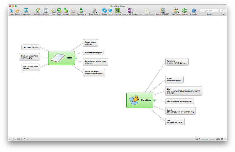
Dealing with Difficult People

Every day we communicate with many people, but sometimes we meet the people with a complex character that do not go towards, in spite of all our efforts. There are about twelve types of people that are recognized as difficult. What we need to do when dealing with a difficult person? Anyway you must realize that you can not avoid the meeting with people, who consciously or unconsciously, will complicate your life. No matter where you are faced with a difficult person - at work, study, or in other occasions, it is needed try to find a compromise, you can use special approaches to dealing with difficult people. The key point in detecting the approach to difficult people is to realize that the person is difficult to communicate, to stay flexible and calm, retain neutrality, to apply to a specific person an individual approach, given its features, hidden needs and interests, and also your own priorities in this situation. Mind Map is a useful way to describe various approaches that you need to take when dealing with difficult people. Make it easy in ConceptDraw MINDMAP software.