How To use House Electrical Plan Software


Circuits and Logic Diagram Software

Building Drawing Software for Designing Plumbing


Network Drawing Software


How To use Switches in Network Diagram

Electrical Symbols — Analog and Digital Logic

The vector stencils library "Logic gate diagram" contains 17 element symbols for drawing the logic gate diagrams.
"To build a functionally complete logic system, relays, valves (vacuum tubes), or transistors can be used. The simplest family of logic gates using bipolar transistors is called resistor-transistor logic (RTL). Unlike simple diode logic gates (which do not have a gain element), RTL gates can be cascaded indefinitely to produce more complex logic functions. RTL gates were used in early integrated circuits. For higher speed and better density, the resistors used in RTL were replaced by diodes resulting in diode-transistor logic (DTL). Transistor-transistor logic (TTL) then supplanted DTL. As integrated circuits became more complex, bipolar transistors were replaced with smaller field-effect transistors (MOSFETs); see PMOS and NMOS. To reduce power consumption still further, most contemporary chip implementations of digital systems now use CMOS logic. CMOS uses complementary (both n-channel and p-channel) MOSFET devices to achieve a high speed with low power dissipation." [Logic gate. Wikipedia]
The symbols example "Design elements - Logic gate diagram" was drawn using the ConceptDraw PRO diagramming and vector drawing software extended with the Electrical Engineering solution from the Engineering area of ConceptDraw Solution Park.
Logic gate symbols

Cisco Network Diagram Software

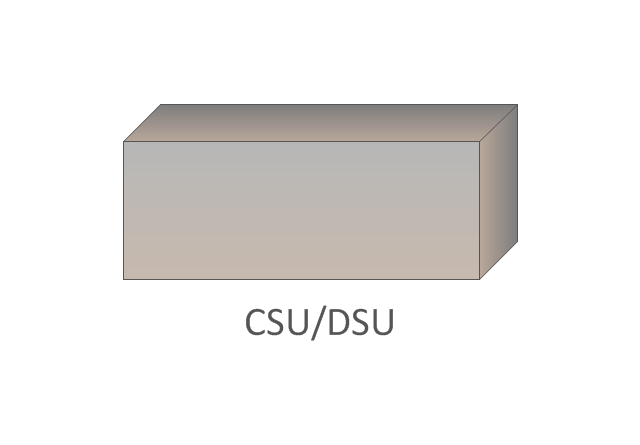
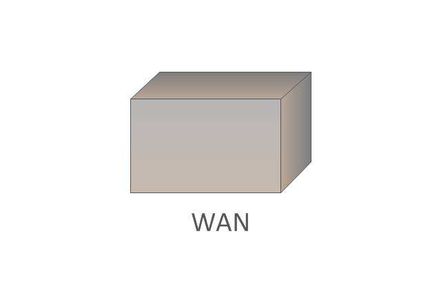
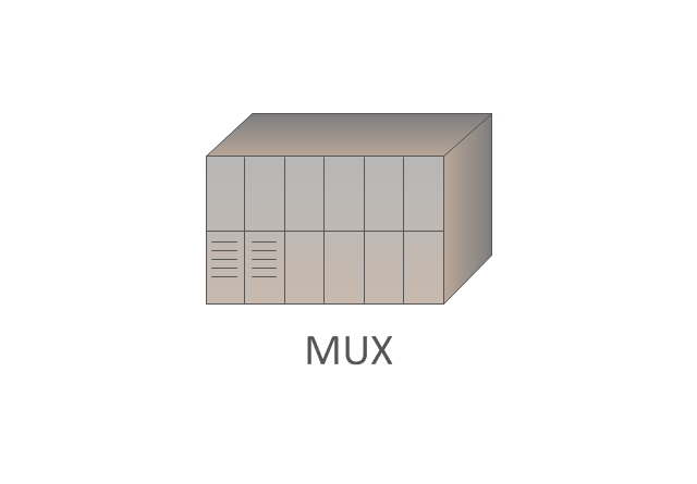
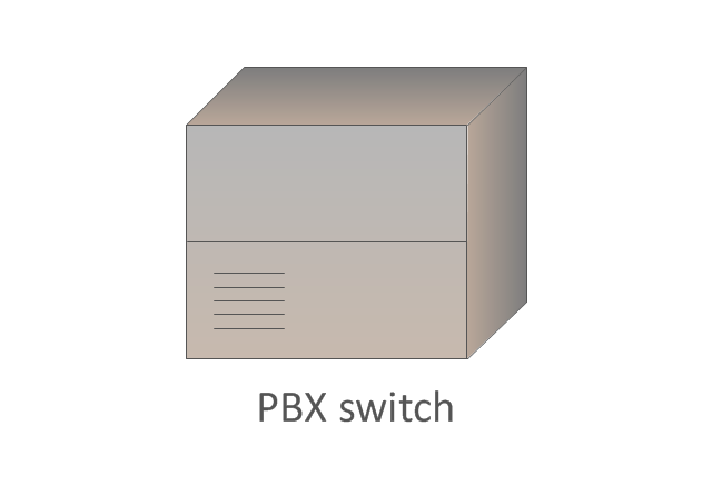
The vector stencils library "Cisco WAN" contains 15 symbols of wide area network (WAN) devices and equipment for drawing Cisco WAN diagrams.
"A wide area network (WAN) is a network that covers a broad area (i.e., any telecommunications network that links across metropolitan, regional, or national boundaries) using leased telecommunication lines. Business and government entities utilize WANs to relay data among employees, clients, buyers, and suppliers from various geographical locations. ...
Related terms for other types of networks are personal area networks (PANs), local area networks (LANs), campus area networks (CANs), or metropolitan area networks (MANs) which are usually limited to a room, building, campus or specific metropolitan area (e.g., a city) respectively.
... it may be best to view WANs as computer networking technologies used to transmit data over long distances, and between different LANs, MANs and other localised computer networking architectures. ...
WANs are often built using leased lines. At each end of the leased line, a router connects the LAN on one side with a second router within the LAN on the other. Leased lines can be very expensive. Instead of using leased lines, WANs can also be built using less costly circuit switching or packet switching methods. Network protocols including TCP/ IP deliver transport and addressing functions. Protocols including Packet over SONET/ SDH, MPLS, ATM and Frame relay are often used by service providers to deliver the links that are used in WANs." [Wide area network. Wikipedia]
The symbols example "Cisco WAN - Vector stencils library" was created using the ConceptDraw PRO diagramming and vector drawing software extended with the Cisco Network Diagrams solution from the Computer and Networks area of ConceptDraw Solution Park.
www.conceptdraw.com/ solution-park/ computer-networks-cisco
CSU/DSU
WAN
MUX
PBX switch
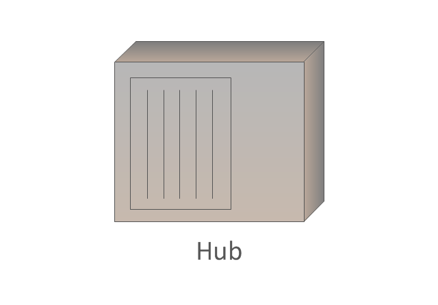
Hub
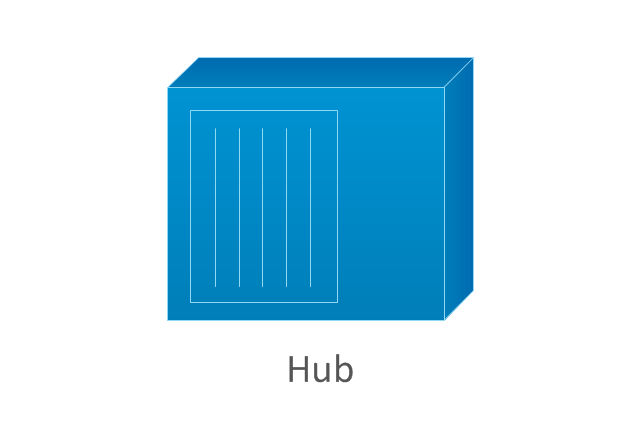
Hub, blue
NAT

Network cloud, dark
Network cloud, gold
Network cloud, white
Network cloud, standard color
Distributed director
Local director
PBX
DPT
The vector stencils library "Cisco network topology" contains 89 symbols of Cisco network devices and design elements for drawing computer network topology diagrams.
"There are two basic categories of network topologies:
(1) Physical topologies,
(2) Logical topologies.
The shape of the cabling layout used to link devices is called the physical topology of the network. This refers to the layout of cabling, the locations of nodes, and the interconnections between the nodes and the cabling. The physical topology of a network is determined by the capabilities of the network access devices and media, the level of control or fault tolerance desired, and the cost associated with cabling or telecommunications circuits.
The logical topology in contrast, is the way that the signals act on the network media, or the way that the data passes through the network from one device to the next without regard to the physical interconnection of the devices." [Network topology. Wikipedia]
The symbols example "Cisco network topology - Vector stencils library" was created using the ConceptDraw PRO diagramming and vector drawing software extended with the Cisco Network Diagrams solution from the Computer and Networks area of ConceptDraw Solution Park.
www.conceptdraw.com/ solution-park/ computer-networks-cisco
Router

Broadband router

Router firewall

Wireless router

Workgroup switch

ATM switch

ISDN switch

Multilayer switch

Protocol translator

Communications server

Transpath

Bridge

Terminal server

Route switch processor

Content engine (cache director)
-cisco-network-topology---vector-stencils-library.png--diagram-flowchart-example.png)
Management engine (ME 1100)
-cisco-network-topology---vector-stencils-library.png--diagram-flowchart-example.png)
Switch processor

ITP

Voice gateway

BBSM

ATA

SIP Proxy server

NetRanger

Cisco 1000

IP

System controller

ACE

Directory server

ADM

Cisco Unity Express

Unity server

Cisco security

CallManager

DSLAM

H.323

CDM (Content Distribution Manager)
-cisco-network-topology---vector-stencils-library.png--diagram-flowchart-example.png)
ICM

Access point

Wireless bridge

Wireless connectivity

Guard

Mobile access router

Carrier Routing System (CRS)
-cisco-network-topology---vector-stencils-library.png--diagram-flowchart-example.png)
Vault

Workstation

PC

Macintosh

Cloud, gold

Cloud, white

Cloud, standard color

Cisco security management

PBX

DPT

Government building

Headquarters, blue

Router in building

Man

Woman

Workgroup switch, subdued

Router, subdued

File server

Firewall, horizontal

Firewall, vertical

Firewall, vertical, subdued

Lock

Key

Lock and key

Car

Truck

File cabinet

Breakout box

Breakout box, blue

Host

Relational database

Modem

BBS (Bulletin Board System)
-cisco-network-topology---vector-stencils-library.png--diagram-flowchart-example.png)
Satellite

Satellite dish

UPS

RPS

MAU

PAD

PAD X.28

Diskette

Contact center

Page icon
Antenna

Antenna, blue

Radio tower

The vector stencils library "Hardware" contains 32 computer hardware and telecommunication equipment icons.
Use it to design your computing and telecom illustrations and infographics with ConceptDraw PRO diagramming and vector drawing software.
The vector stencils library "Hardware" is included in the Computers and Communications solution from the Illustration area of ConceptDraw Solution Park.
Use it to design your computing and telecom illustrations and infographics with ConceptDraw PRO diagramming and vector drawing software.
The vector stencils library "Hardware" is included in the Computers and Communications solution from the Illustration area of ConceptDraw Solution Park.
Rack

Workstation

Monitor with keyboard

Laptop

Laptop settings

Keyboard connection

Keyboard with mouse

Keyboard
USB computer mouse
WiFi mouse

Webcam

Remote control
Hard drive

Flash drive

Floppy
CPU
Hard drive
SD card
8GB memory card
Battery
Battery charging

Accumulator

Cable connector
Power socket
Power plug

USB cable
Electric bulb

Voltage meter
Speed control

Router
Modem
Bluetooth device

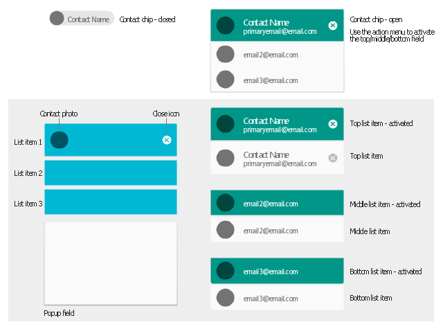
The vector stencils library "Android chips" contains 14 chip elements: contact chips, list items, popup field, contact photo, close icon.
Use it to design user interface of your Android application.
The shapes example "Design elements - Android chips" was created using the ConceptDraw PRO diagramming and vector drawing software extended with the "Android user interface" solution from the "Software Development" area of ConceptDraw Solution Park.
Chip elements
Classroom Layout

How to Create Cisco Network Diagram

- Mechanical Engineering | Mechanical Drawing Software ...
- Mechanical Schematic Drawing
- Drawing Cctv Layout
- Software For Drawing Electrical Circuit For Android
- CCTV Network Example | How To Create CCTV Network Diagram ...
- Logic gate diagram - Template | Circuits and Logic Diagram ...
- Chemical and Process Engineering | Technical Drawing Software ...
- Design elements - Cabinets and bookcases | How To use House ...
- Android 5.0 - App drawer | Android 5.0 - Gmail | Android 5.0 - Lock ...
- Android 5.0 - Gmail | Android 5.0 - App drawer | Android 5.0 - Lock ...
- Cabinets and bookcases - Vector stencils library | Long Counter ...
- Cabinets and bookcases - Vector stencils library | How To Make ...
- Electrical Symbols, Electrical Diagram Symbols | Network Glossary ...
- Switches and relays - Vector stencils library | Design elements ...
- How to Draw a Chemical Process Flow Diagram | Design elements ...
- Telecom - Vector stencils library | Guesthouse Network. WIFI ...
- Drawing Simple Road Map Software
- Mesh Network Topology Diagram | Mesh Network. Computer and ...
- 5 Level pyramid model diagram - Information systems types ...
- Card Design In Android