Booch OOD Diagram
The vector stencils library Booch OOD from the solution Software Engineering contains specific symbols of the Booch method such as class symbols, association symbols, aggregation symbols for ConceptDraw DIAGRAM diagramming and vector drawing software. The Software Engineering solution is contained in the Software Development area of ConceptDraw Solution Park.UML Flowchart Symbols
The UML diagram is a powerful tool which lets visually represent all system's components, the interactions between them and relationships with external user interface. The Rapid UML solution for ConceptDraw DIAGRAM software offers diversity of UML flowchart symbols for drawing all types of UML diagrams.UML Class Diagram Notation
When it comes to system construction, a class diagram is the most widely used diagram. UML Class Diagrams is a type of static structure diagram that is used for general conceptual modeling of the systematics of the application. Such a diagram would illustrate the object-oriented view of a system. The object orientation of a system is indicated by a class diagram. It describes the structure of a system by showing the general issues,classes of a system, attributes, operations, interfaces, inheritance, and the relationships between them.UML Diagrams with ConceptDraw DIAGRAM
Unified Modeling Language (UML) is a single modeling language that is used in software engineering to represent effectively the structure of complex computer systems and software. Such visual models in form of UML diagrams allow simplify the process of software development, let to meet the deadlines, improve the final software products, and also facilitate communication process between the customer, system analysts and programmers. The UML language defines standards for operations, methods of programming languages, and their terminology. The main types of UML diagrams are: Activity diagram, Use Case diagram, Deployment diagram, Statechart diagram, Class diagram, Component diagram, Sequence diagram, Collaboration diagram. ConceptDraw DIAGRAM extended with Rapid UML solution is a professional software that provides perfect possibility of easy designing detailed UML diagrams. It offers large number of task-oriented templates and predesigned vector stencils that correspond to standard UML diagram notation. Use them to instantly design the UML diagrams.Software Diagram Examples and Templates
ConceptDraw DIAGRAM is a powerful tool for business and technical diagramming. Software Development area of ConceptDraw Solution Park provides 5 solutions: Data Flow Diagrams, Entity-Relationship Diagram (ERD), Graphic User Interface, IDEFO Diagrams, Rapid UML.Interaction Overview Diagram
UML Interaction Overview Diagram schematically shows a control flow with nodes and a sequence of activities that can contain interaction or sequence diagrams.
SDL — Systems Engineering
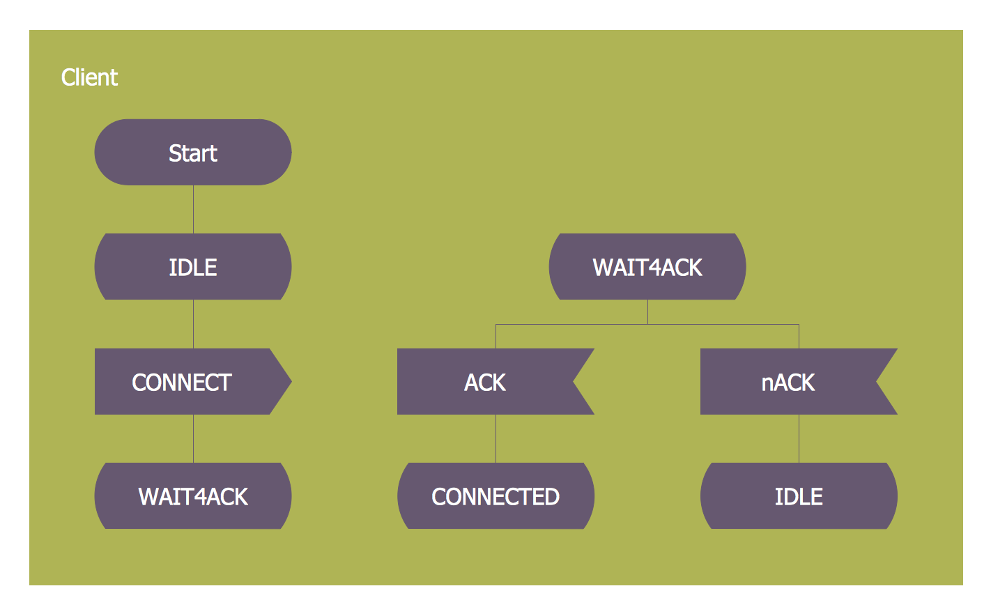
How to design SDL Diagram fast and easy? ConceptDraw DIAGRAM diagramming and vector drawing software supplied with unique Specification and Description Language (SDL) Solution from the Industrial Engineering Area of ConceptDraw Solution Park will help you design SDL Diagram of any complexity without efforts- Booch OOD Diagram | UML Diagram for Mac | UML Notation | State ...
- Simple State Transition Diagram Example
- Booch OOD Diagram | Object-Oriented Development (OOD) Method ...
- UML State Machine Diagram .Design Elements | Booch OOD ...
- Booch OOD Diagram | UML State Machine Diagram .Design ...
- UML Class Diagram Example - Medical Shop | State Diagram ...
- UML state machine diagram - State transitions of RT-component ...
- UML state machine diagram - Template | Rapid UML | Design ...
- Schematic Diagram Showing Process State
- State Diagram Example — Online Store | UML State Machine ...
- State Diagram Example — Online Store | UML State Machine ...
- Transition schematic - IDEF3 diagram example | Completed ...
- UML state machine diagram - State transitions of RT-component ...
- Difference Between Statechart And State Transition Diagram
- Diagramming Software for Design UML State Machine Diagrams ...
- Design elements - Soccer (Football) positions | Design elements ...
- State Transition Diagram Template
- State Diagram Example — Online Store | Stakeholder Management ...
- How to create an IDEF3 diagram using ConceptDraw PRO | Vector ...
- Software development with ConceptDraw DIAGRAM | | Design ...


