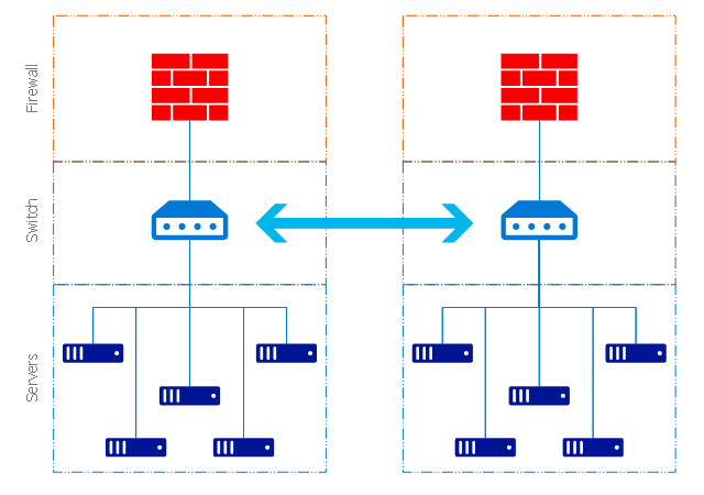
"The client–server model of computing is a distributed application structure that partitions tasks or workloads between the providers of a resource or service, called servers, and service requesters, called clients. Often clients and servers communicate over a computer network on separate hardware, but both client and server may reside in the same system. A server host runs one or more server programs which share their resources with clients. A client does not share any of its resources, but requests a server's content or service function. Clients therefore initiate communication sessions with servers which await incoming requests.
Examples of computer applications that use the client–server model are Email, network printing, and the World Wide Web." [Client–server model. Wikipedia]
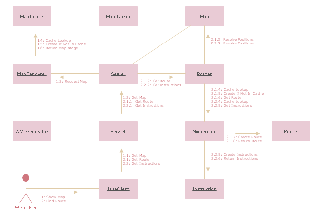
The UML communication diagram example "Client server access" was created using the ConceptDraw PRO diagramming and vector drawing software extended with the Rapid UML solution from the Software Development area of ConceptDraw Solution Park.
"A server is a system (software and suitable computer hardware) that responds to requests across a computer network to provide, or help to provide, a network service. Servers can be run on a dedicated computer, which is also often referred to as "the server", but many networked computers are capable of hosting servers. In many cases, a computer can provide several services and have several servers running.
Servers operate within a client-server architecture. Servers are computer programs running to serve the requests of other programs, the clients. Thus, the server performs some tasks on behalf of clients. The clients typically connect to the server through the network but may run on the same computer. In the context of Internet Protocol (IP) networking, a server is a program that operates as a socket listener.
Servers often provide essential services across a network, either to private users inside a large organization or to public users via the Internet. Typical computing servers are database server, file server, mail server, print server, web server, gaming server, application server, or some other kind of server.
Numerous systems use this client / server networking model including Web sites and email services. An alternative model, peer-to-peer networking enables all computers to act as either a server or client as needed." [Server (computing). Wikipedia]
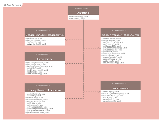
The UML component diagram example "Start server" was created using the ConceptDraw PRO diagramming and vector drawing software extended with the Rapid UML solution from the Software Development area of ConceptDraw Solution Park.
The vector stencils library "Telecommunication networks" contains 32 clipart images of telecommunication network devices and equipment for drawing telecom network diagrams.
"A telecommunications network is a collection of terminal nodes, links and any intermediate nodes which are connected so as to enable telecommunication between the terminals.
The transmission links connect the nodes together. The nodes use circuit switching, message switching or packet switching to pass the signal through the correct links and nodes to reach the correct destination terminal.
Each terminal in the network usually has a unique address so messages or connections can be routed to the correct recipients. The collection of addresses in the network is called the address space." [Telecommunications network. Wikipedia]
The clip art example "Telecommunication networks - Vector stencils library" was created using the ConceptDraw PRO diagramming and vector drawing software extended with the Telecommunication Network Diagrams solution from the Computer and Networks area of ConceptDraw Solution Park.
Server rack diagrams visualize the rack mounting of a computer and network equipment as a frontal view of the rack with the equipment installed. They are used when choosing which equipment or racks to buy, and to see if a particular configuration works, without having to go through a physical install.
"In the hardware sense, the word server typically designates computer models intended for hosting software applications under the heavy demand of a network environment. In this client–server configuration, one or more machines, either a computer or a computer appliance, share information with each other with one acting as a host for the other[s].
While nearly any personal computer is capable of acting as a network server, a dedicated server will contain features making it more suitable for production environments. These features may include a faster CPU, increased high-performance RAM, and increased storage capacity in the form of a larger or multiple hard drives. Servers also typically have reliability, availability and serviceability (RAS) and fault tolerance features, such as redundancy in power supplies, storage (as in RAID), and network connections." [Server (computing). Wikipedia]
This network server rack diagram example was created using the ConceptDraw PRO diagramming and vector drawing software extended with the Rack Diagrams solution from the Computer and Networks area of ConceptDraw Solution Park.
The vector stencils library "Computer network" contains 51 symbols of computer network devices and equipment for drawing computer network diagrams.
"Network Mapping Software.
A number of software tools exist to design computer network diagrams / or generate visual maps of networks, servers, storage, services, data centers, and other peripherals. Broadly, there are two types of software tools - those that help create diagrams manually and those that generate them using automated / semi-automated approaches.
Type of Software.
(1) Manual - allows users to design and draw logical and physical topology diagrams by manually placing icons and connections.
(2) Automated - generate topology diagrams / maps by traversing the network and automatically discovering resident devices or by importing network data." [Comparison of network diagram software. Wikipedia]
ConceptDraw PRO is the software for manual design of computer network diagrams. The solutions of the Computer and Networks area in ConceptDraw Solution Park extend ConceptDraw PRO with vector stencils libraries, templates and examples for creating the computer network diagrams.
The symbols example "Computer network - Vector stencils library" was created using the ConceptDraw PRO diagramming and vector drawing software extended with the Computer and Networks solution from the Computer and Networks area of ConceptDraw Solution Park.
www.conceptdraw.com/ solution-park/ computer-and-networks
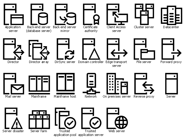
The vector stencil library "Azure architecture - Servers" contains 26 computer network server icons.
Use these computer network server symbols to draw Azure architecture diagrams with ConceptDraw PRO software.
"In computing, a server is a computer program or a device that provides functionality for other programs or devices, called "clients". This architecture is called the client–server model, and a single overall computation is distributed across multiple processes or devices. Servers can provide various functionalities, often called "services", such as sharing data or resources among multiple clients, or performing computation for a client. A single server can serve multiple clients, and a single client can use multiple servers. A client process may run on the same device or may connect over a network to a server on a different device. Typical servers are database servers, file servers, mail servers, print servers, web servers, game servers, and application servers." [Server (computing). Wikipedia]
The computer network server icon set example "Design elements - Azure architecture - Servers" is included in Azure Architecture solution from Computer and Networks area of ConceptDraw Solution Park.
The vector stencils library "Computers and network isometric" contains 56 3D clipart images of computer and network devices and equipment for drawing network diagrams.
The clip art example "Computers and network isometric - Vector stencils library" was created using the ConceptDraw PRO diagramming and vector drawing software extended with the Computer and Networks solution from the Computer and Networks area of ConceptDraw Solution Park.
The clip art example "Computers and network isometric - Vector stencils library" was created using the ConceptDraw PRO diagramming and vector drawing software extended with the Computer and Networks solution from the Computer and Networks area of ConceptDraw Solution Park.
Network Glossary Definition
The network glossary contains a complete list of network, computer-related and technical terms in alphabetic order, explanations and definitions for them, among them there are words well known for you and also specific, rare-used, uncommon or newly introduced terms. This specialized glossary, also known as a vocabulary, is the best in its field and covers in details the various aspects of computer network technologies. This glossary was developed by specialists using the practical experience and many useful sources to help the ConceptDraw users in their work, you can read and learn it from the screen on-line or print, it can be also used as a perfect educational guide or tutorial. ConceptDraw DIAGRAM software extended with Computer and Networks solution is easy to draw various types of Network diagrams, Network topology diagrams, Computer networking schematics, Network maps, Cisco network topology, Computer network architecture, Wireless networks, Vehicular networks, Rack diagrams, Logical, Physical, Cable networks, etc. Desktop ConceptDraw DIAGRAM Software is a good Visio for Mac Os X replacement. It gives you rich productivity and quality of the produced diagrams.
 PM Agile
PM Agile solution provides powerful tools for project management, project planning and software development, ensuring support of Agile methods, assisting in holding the Scrum-meetings, collaborative planning sprints, maintaining backlog, calculating and reporting the velocity of the team. Intended for the companies using Agile methodology, specifically Scrum, Product Owners, Scrum Masters, software developers, and management specialists, this solution includes examples demonstrating the main principles of Agile methodology and Scrum, and numerous templates specially developed in ConceptDraw DIAGRAM and ConceptDraw MINDMAP applications. All Agile meetings and documents are powered by the mission of adapted Mind Map templates, tuned for collaborative work of development team. The key diagrams for visualization are made in ConceptDraw DIAGRAM.
 Rapid UML
Rapid UML solution extends ConceptDraw DIAGRAM software with templates, samples and libraries of vector stencils for quick drawing the UML diagrams using Rapid Draw technology.
The vector stencils library "Microsoft Exchange" contains 17 symbols of Microsoft Exchange elements for drawing the logical structure diagrams of Active Directory trees.
"Windows Messaging, initially called Microsoft Exchange, is an e-mail client that was included with Windows 95 (beginning with OSR2), 98 and Windows NT 4.0. ...
Microsoft Exchange gained wide usage with the release of Windows 95, as this was the only mail client that came bundled with it. In 1996, it was renamed to Windows Messaging, because of the upcoming release of Microsoft Exchange Server, and continued to be included throughout later releases of Windows up until the initial release of Windows 98, which by then included Outlook Express 4.0 as the default mail client.
The Windows Messaging email client had two branches of successors:
(1) In software bundled with Windows itself, these were Internet Mail and News in Windows 95 (and bundled with Internet Explorer 3), which was succeeded by Outlook Express 4.0 in Windows 98 (bundled with Internet Explorer 4.0 in Windows 95) and throughout newer Windows systems. These did not use the .pst file type.
(2) Microsoft Outlook became the professional-grade and more direct successor of MS Exchange Client, which still uses the .pst file type." [Windows Messaging. Wikipedia]
The symbols example "Microsoft Exchange - Vector stencils library" was created using the ConceptDraw PRO diagramming and vector drawing software extended with the Active Directory Diagrams solution from the Computer and Networks area of ConceptDraw Solution Park.
www.conceptdraw.com/ solution-park/ active-directory-diagrams
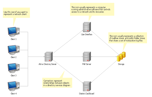
Active Directory Diagrams visualize the detail structures of the Microsoft Windows networks, Active Directory Domain topology, the Active Directory Site topology, the Organizational Units (OU), and the Exchange Server Organization. They are used to visually document the Microsoft Active Directory network detail structure for network designing, and for managing the control access to printers and files, the access and security, the traffic flow optimization in local and wide area nets, the network equipment maintenance and repair, the data backup, storage, and recovery.
The Active Directory diagram template for the ConceptDraw PRO diagramming and vector drawing software is included in the Active Directory Diagrams solution from the Computer and Networks area of ConceptDraw Solution Park.
The Active Directory diagram template for the ConceptDraw PRO diagramming and vector drawing software is included in the Active Directory Diagrams solution from the Computer and Networks area of ConceptDraw Solution Park.
Diagramming Software for Design UML Collaboration Diagrams
ConceptDraw helps you to start designing your own UML Collaboration Diagrams with examples and templates.
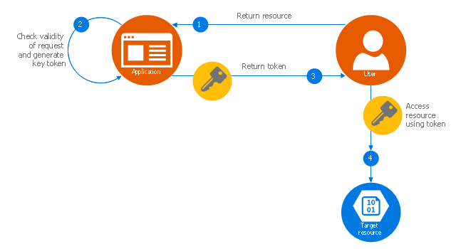
This Azure cloud architecture pattern diagram template was created on the base of figure in the article "Valet Key Pattern" from the Microsoft Developer Network (MSDN) website.
"Valet Key Pattern.
Use a token or key that provides clients with restricted direct access to a specific resource or service in order to offload data transfer operations from the application code. This pattern is particularly useful in applications that use cloud-hosted storage systems or queues, and can minimize cost and maximize scalability and performance. ...
Client programs and web browsers often need to read and write files or data streams to and from an application’s storage. ...
Data stores have the capability to handle upload and download of data directly, without requiring the application to perform any processing to move this data, but this typically requires the client to have access to the security credentials for the store.
... applications must be able to securely control access to data in a granular way, but still reduce the load on the server by setting up this connection and then allowing the client to communicate directly with the data store to perform the required read or write operations. ...
To resolve the problem of controlling access to a data store where the store itself cannot manage authentication and authorization of clients, one typical solution is to restrict access to the data store’s public connection and provide the client with a key or token that the data store itself can validate.
This key or token is usually referred to as a valet key. It provides time-limited access to specific resources and allows only predefined operations such as reading and writing to storage or queues, or uploading and downloading in a web browser. Applications can create and issue valet keys to client devices and web browsers quickly and easily, allowing clients to perform the required operations without requiring the application to directly handle the data transfer. This removes the processing overhead, and the consequent impact on performance and scalability, from the application and the server." [msdn.microsoft.com/ ru-RU/ library/ dn568102.aspx]
The Azure cloud system architecture diagram template "Valet key pattern" for the ConceptDraw PRO diagramming and vector drawing software is included in the Azure Architecture solutin from the Computer and Networks area of ConceptDraw Solution Park.
This example of cloud computing system architecture diagram was redesigned from the Wikimedia Commons file: ArchitectureCloudLinksSameSite.png. [commons.wikimedia.org/ wiki/ File:ArchitectureCloudLinksSameSite.png]
"An example showing a grid computing system connecting many personal computers over the Internet using inter-process network communication ...
In computer science, inter-process communication (IPC) is the activity of sharing data across multiple and commonly specialized processes using communication protocols. Typically, applications using IPC are categorized as clients and servers, where the client requests data and the server responds to client requests." [en.wikipedia.org/ wiki/ Inter-process_ communication]
"Grid computing is the collection of computer resources from multiple locations to reach a common goal. The grid can be thought of as a distributed system with non-interactive workloads that involve a large number of files. Grid computing is distinguished from conventional high performance computing systems such as cluster computing in that grid computers have each node set to perform a different task/ application. Grid computers also tend to be more heterogeneous and geographically dispersed (thus not physically coupled) than cluster computers." [Grid computing. Wikipedia]
The diagram example "Grid computing system architecture" was created using ConceptDraw PRO diagramming and vector drawing software extended with the Azure Architecture solution from the Computer and Networks area of ConceptDraw Solution Park.
"Request methods.
An HTTP 1.1 request made using telnet. The request, response headers and response body are highlighted.
HTTP defines methods (sometimes referred to as verbs) to indicate the desired action to be performed on the identified resource. What this resource represents, whether pre-existing data or data that is generated dynamically, depends on the implementation of the server. Often, the resource corresponds to a file or the output of an executable residing on the server. The HTTP/ 1.0 specification:section 8 defined the GET, POST and HEAD methods and the HTTP/ 1.1 specification:section 9 added 5 new methods: OPTIONS, PUT, DELETE, TRACE and CONNECT. By being specified in these documents their semantics are well known and can be depended upon. Any client can use any method and the server can be configured to support any combination of methods. If a method is unknown to an intermediate it will be treated as an unsafe and non-idempotent method. There is no limit to the number of methods that can be defined and this allows for future methods to be specified without breaking existing infrastructure. For example, WebDAV defined 7 new methods and RFC5789 specified the PATCH method.
GET.
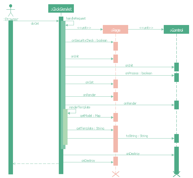
Requests a representation of the specified resource. Requests using GET should only retrieve data and should have no other effect. (This is also true of some other HTTP methods.)" [Hypertext Transfer Protocol. Wikipedia]
The UML sequence diagram example "GET request" was created using the ConceptDraw PRO diagramming and vector drawing software extended with the Rapid UML solution from the Software Development area of ConceptDraw Solution Park.
Active Directory Diagram
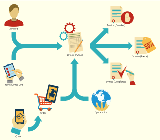
Active Directory (AD) is a directory management service introduced by Microsoft Corporation for Windows domain networks. This service uses the Lightweight Directory Access Protocol (LDAP) and provides quick access to the included information about large structural units such as domains, organizational units, sites, and also about simple objects, such as users names with detailed information about them - contacts information, access rights, etc. Active Directory Diagram is a representation of the network structure in clear graphical format. It is a scheme of correlations of service components with preset degree of detailed elaboration. Active Directory Diagram makes the work of network administrators with Active Directory network structure more easy and convenient, allows plan and service the network quicker and more qualitatively. The help of ConceptDraw DIAGRAM software extended with Active Directory Diagrams solution from the Computer and Networks area is indispensable for easily and quickly creation the highly detailed Active Directory Diagrams.This flowchart example shows the lifecycle of an invoice in Microsoft Dynamics CRM. It was redesigned from the Wikimedia Commons file: Invoice lifecycle.svg. [commons.wikimedia.org/ wiki/ File:Invoice_ lifecycle.svg]
"Microsoft Dynamics CRM is a customer relationship management software package developed by Microsoft. Out of the box, the product focuses mainly on Sales, Marketing, and Service (help desk) sectors...
Dynamics CRM is a server-client application, which, like Microsoft SharePoint, is primarily an IIS-based web application which also supports extensive web services interfaces. Clients access Dynamics CRM either by using a Browser or by a thick client plug-in to Microsoft Outlook." [Microsoft Dynamics CRM. Wikipedia]
The process flowchart example "Invoice lifecycle" was created using the ConceptDraw PRO diagramming and vector drawing software extended with the Sales Flowcharts solution from the Marketing area of ConceptDraw Solution Park.
This exaple was resigned from the Wikimedia Commons file: Mobile Cloud Architecture.jpg. [commons.wikimedia.org/ wiki/ File:Mobile_ Cloud_ Architecture.jpg]
This file is licensed under the Creative Commons Attribution-Share Alike 3.0 Unported license. [creativecommons.org/ licenses/ by-sa/ 3.0/ deed.en]
This diagram describes general architecture of Mobile Cloud Computing.
Legend.
BTS: Base Transceiver Station.
AAA: Network Authentication, Authorization, and Accounting.
HA: Home Agent.
"Mobile/ cloud computing is the combination of cloud computing and mobile networks to bring benefits for mobile users, network operators, as well as cloud computing providers. The ultimate goal of MCC (mean of MCC is Mobile/ Cloud Computing) is to enable execution of rich mobile applications on a plethora of mobile devices, with a rich user experience. MCC provides business opportunities for mobile network operators as well as cloud providers." [Mobile cloud computing. Wikipedia]
The example "Mobile cloud architecture diagram" was created using the ConceptDraw PRO diagramming and vector drawing software extended with the AWS Architecture Diagrams solution from the Computer and Networks area of ConceptDraw Solution Park.
The vector stencils library "Azure architecture - Enterprise" contains 98 Microsoft Azure architecture symbols.
Use this enterprise cloud icon set to design your cloud computing architecture diagrams.
"Enterprise cloud computing is the special case of utilizing cloud computing for competitive advantage through breakout opportunities both for cost savings and, more importantly, for business innovation in terms of unprecedented speed and agility with vastly improved collaboration among business partners and customers." [whatis.techtarget.com/ definition/ Enterprise-Cloud-Computing-FAQ]
The symbols example "Design elements - Azure architecture - Enterprise" is included in the Azure Architecture solution from the Computer and Networks area of ConceptDraw Solution Park.
- UML communication diagram - Client server access | Rapid UML ...
- UML communication diagram - Client server access | UML use case ...
- UML communication diagram - Client server access | Client Server ...
- UML communication diagram - Client server access | How to Draw a ...
- Server hardware - Rack diagram | UML component diagram - Start ...
- UML communication diagram - Client server access | Databases ...
- UML communication diagram - Client server access | Logical ...
- UML communication diagram - Client server access | ConceptDraw ...
- Server | Server hardware - Rack diagram | UML component diagram ...
- UML communication diagram - Client server access | Idea ...
- Amazon Client Server Architecture
- Class Diagram For Email Client Server System
- Server hardware - Rack diagram | UML communication diagram ...
- Use Case Diagram For Email Client System
- Erd Client Server
- UML communication diagram - Client server access
- Web Client Server Architecture Diagram
- UML communication diagram - Client server access | Windows 10 ...
- Dfd Of Client Server System
