UML Use Case Diagram Example Social Networking Sites Project
UML Diagrams Social Networking Sites Project. This sample was created in ConceptDraw PRO diagramming and vector drawing software using the UML Use Case Diagram library of the Rapid UML Solution from the Software Development area of ConceptDraw Solution Park. This sample shows the Facebook Socio-health system and is used at the projection and creating of the social networking sites.How to Build Cloud Computing Diagram Principal Cloud Manufacturing
The term “cloud” is very popular and widely used now, it is a server, data processing centre, or a network which lets to store the data and software, provides access to them, allows to run applications without installation and gives the possibility to process data hosted remotely via the Internet connection. For documenting the Cloud Computing Architecture with a goal to facilitate the communication between stakeholders are successfully used the Cloud Computing Architecture diagrams. It is convenient and easy to draw various Cloud Computing Architecture diagrams in ConceptDraw PRO software with help of tools of the Cloud Computing Diagrams Solution from the Computer and Networks Area of ConceptDraw Solution Park.
 Data Flow Diagrams (DFD)
Data Flow Diagrams solution extends ConceptDraw PRO software with templates, samples and libraries of vector stencils for drawing the data flow diagrams (DFD).
 ConceptDraw Solution Park
ConceptDraw Solution Park collects graphic extensions, examples and learning materials
Microsoft Azure
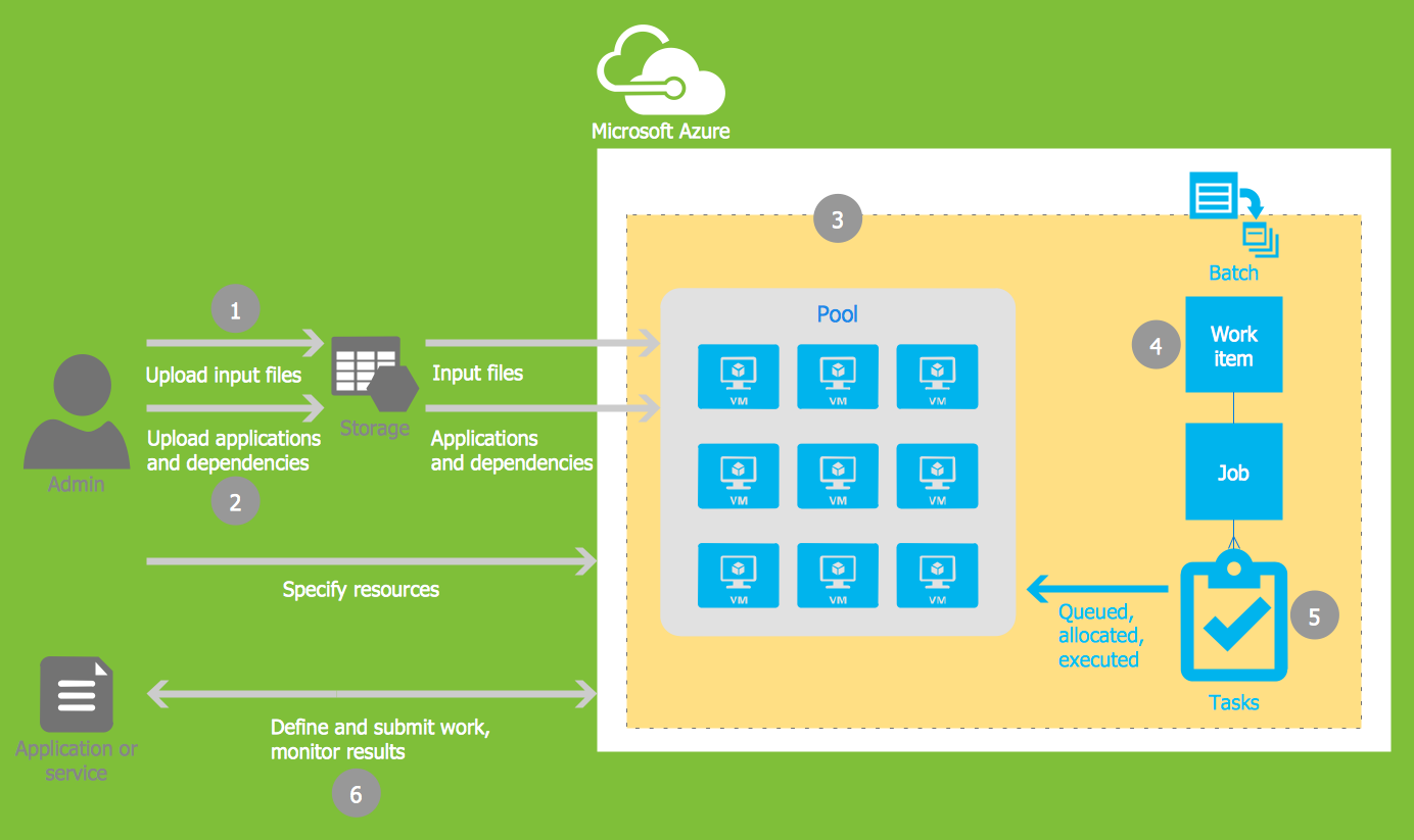
Microsoft Azure is widely used cloud platform which was created by Microsoft and now is managed by Microsoft datacenters in 19 regions of the world, and has a wide set of benefits and features. ConceptDraw PRO diagramming and vector drawing software extended with Azure Architecture Solution from the Computer and Networks area of ConceptDraw Solution Park is the best for designing various pictorial infographics, illustrations and materials showing the possibilities and work of Microsoft Azure Cloud System and Azure services.JSD - Jackson system development
Jackson System Development (JSD) is a linear method of system development created by Michael A. Jackson and John Cameron in the 1980s. It comprises the whole software life cycle directly or providing a framework for more specialized techniques. When implementing the Jackson System Development method and designing JSD diagrams, you can succesfully use the powerful and helpful tools of ConceptDraw PRO software extended with Entity-Relationship Diagram (ERD) solution from the Software Development area of ConceptDraw Solution Park.Flowchart Example: Flow Chart of Marketing Analysis
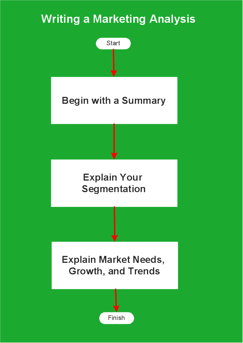
An example flowchart of marketing analysis shows main steps you have to challenge writing a marketing analysis.
 Cloud Computing Diagrams
The Cloud Computing Diagrams solution extends the functionality of the ConceptDraw PRO v10 software with comprehensive collection of libraries of cloud computing vector stencils to help you get started design of Cloud Computing Diagrams and Architecture D
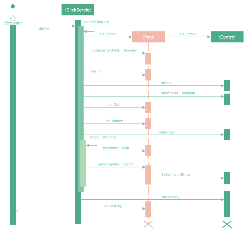
Sequence Diagram for Cloud Computing
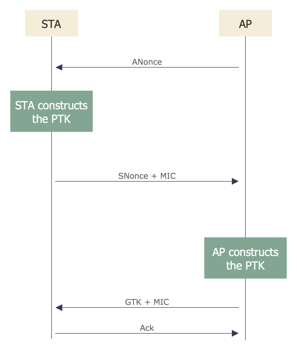
One of the ways effectively visualize what is a Cloud computing or Cloud computing architecture, is to create the Sequence diagram for Cloud computing. The ConceptDraw PRO diagramming and vector drawing software enhanced with Cloud Computing Diagrams solution from the Computers and Network area of ConceptDraw Solution Park will help you design all desired types of diagrams related with cloud computing.Introduction to Cloud Computing Architecture
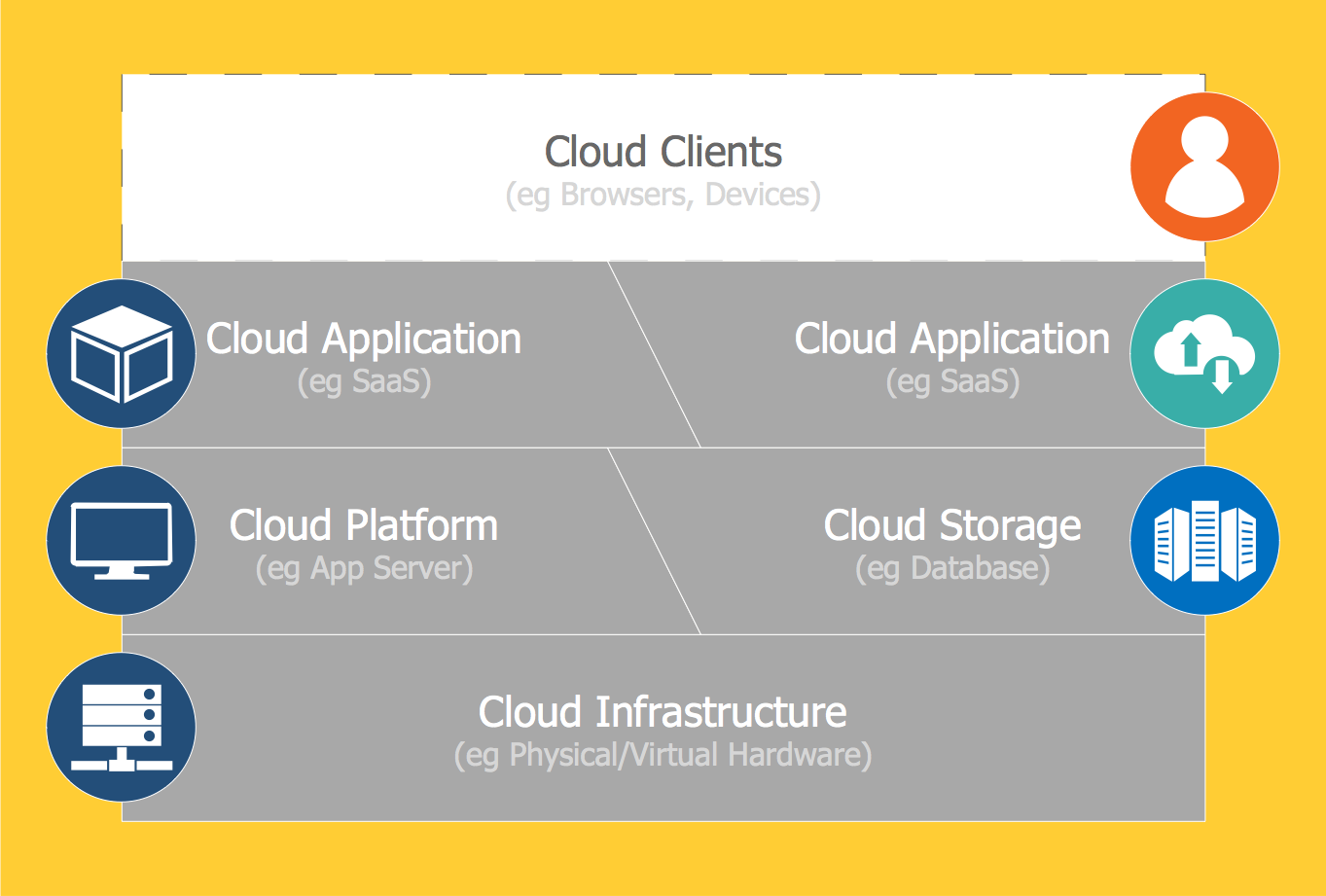
The best way to visualize the introduction to Cloud computing architecture is to create diagrams and schematics representing what is a cloud computing and how it works. For their design, we recommend to use a powerful ConceptDraw PRO diagramming and vector drawing software supplied with Cloud Computing Diagrams solution from the Computers and Network area of ConceptDraw Solution ParkSequence Diagram Tool
ConceptDraw PRO diagramming and vector drawing software as a sequence diagram tool provides the Rapid UML Solution from the Software Development Area that contains the UML Sequence library.
 Entity-Relationship Diagram (ERD)
An Entity-Relationship Diagram (ERD) is a visual presentation of entities and relationships. That type of diagrams is often used in the semi-structured or unstructured data in databases and information systems. At first glance ERD is similar to a flowch
 ATM UML Diagrams
The ATM UML Diagrams solution lets you create ATM solutions and UML examples. Use ConceptDraw PRO as a UML diagram creator to visualize a banking system.
- Cloud Computing Architecture Diagrams | Introduction to Cloud ...
- Cloud Computing | CERES data flow diagram | Amazon Cloud ...
- ER Diagram for Cloud Computing | Example of DFD for Online Store ...
- Data Flow Diagram ( DFD ) | ER Diagram for Cloud Computing ...
- Data Flow Diagram Symbols. DFD Library | How to Build Cloud ...
- ER Diagram for Cloud Computing | Process Flowchart | Example of ...
- Computer and Networks Area | Cloud Computing Diagrams | Data ...
- AWS Architecture Diagrams | Cloud Computing Diagrams ...
- Active Directory Diagrams | Data Flow Diagrams ( DFD ) | Cloud ...
- Storage area networks (SAN). Computer and Network Examples ...
- How to Build Cloud Computing Diagram Principal Cloud ...
- Data Flow Diagram ( DFD ) | Entity-Relationship Diagram (ERD) | ER ...
- Data Flow Diagrams | ER Diagram for Cloud Computing | Entity ...
- Example of DFD for Online Store ( Data Flow Diagram ) DFD ...
- Data Flow Diagram Symbols. DFD Library
- Data Flow Diagrams ( DFD ) | ConceptDraw Solution Park ...
- Metro Map | How to Build Cloud Computing Diagram Principal ...
- IDEF0 Diagrams | How to Build Cloud Computing Diagram Principal ...
- Entity-Relationship Diagram (ERD) | Example of DFD for Online ...
- What is Cloud Computing | Introduction to Cloud Computing ...


