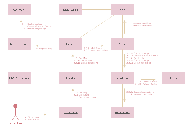
"The client–server model of computing is a distributed application structure that partitions tasks or workloads between the providers of a resource or service, called servers, and service requesters, called clients. Often clients and servers communicate over a computer network on separate hardware, but both client and server may reside in the same system. A server host runs one or more server programs which share their resources with clients. A client does not share any of its resources, but requests a server's content or service function. Clients therefore initiate communication sessions with servers which await incoming requests.
Examples of computer applications that use the client–server model are Email, network printing, and the World Wide Web." [Client–server model. Wikipedia]
The UML communication diagram example "Client server access" was created using the ConceptDraw PRO diagramming and vector drawing software extended with the Rapid UML solution from the Software Development area of ConceptDraw Solution Park.
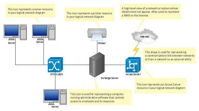
"... logical topology shows how data flows within a network, regardless of its physical design. ...
The logical topology in contrast, is the way that the signals act on the network media, or the way that the data passes through the network from one device to the next without regard to the physical interconnection of the devices. A network's logical topology is not necessarily the same as its physical topology." [Network topology. Wikipedia]
The logical network diagram template for the ConceptDraw PRO diagramming and vector drawing software is included in the Computer and Networks solution from the Computer and Networks area of ConceptDraw Solution Park.
 AWS Architecture Diagrams
The flexible AWS cloud solutions will help you to create reliable applications with a high level of scaling in the AWS cloud, to run your applications and accelerate their work on the level of security. Besides AWS resources are available worldwide and yo
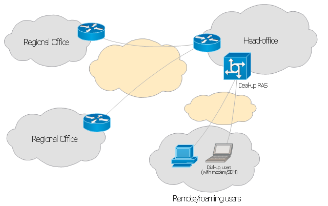
This Cisco network diagram example was redesigned from the Wikimedia Commons file: EPN Frame-Relay and Dial-up Network.svg.
[commons.wikimedia.org/ wiki/ File:EPN_ Frame-Relay_ and_ Dial-up_ Network.svg]
This file is licensed under the Creative Commons Attribution-Share Alike 3.0 Unported license. [creativecommons.org/ licenses/ by-sa/ 3.0/ deed.en]
This diagram depicts enterprise private network (EPN) using frame-relay and dial-up.
"An enterprise private network is a computer network built by a business to interconnect its various company sites (such as production sites, offices and shops) in order to share computer resources." [Enterprise private network. Wikipedia]
"Dial-up Internet access is a form of Internet access that uses the facilities of the public switched telephone network (PSTN) to establish a dialed connection to an Internet service provider (ISP) via telephone lines. The user's computer or router uses an attached modem to encode and decode Internet Protocol packets and control information into and from analogue audio frequency signals, respectively. Dial-up internet is sometimes used where Broadband internet access is not available; primarily in rural or remote areas." [Dial-up Internet access. Wikipedia]
The example "Enterprise private network" was created using the ConceptDraw PRO diagramming and vector drawing software extended with the Cisco Network Diagrams solution from the Computer and Networks area of ConceptDraw Solution Park.
- Server hardware - Rack diagram | UML component diagram - Start ...
- Communication network diagram | Cisco Network Topology. Cisco ...
- Mobile satellite communication network diagram
- UML communication diagram - Client server access | Idea Outline ...
- UML communication diagram - Client server access | Diagramming ...
- UML communication diagram - Client server access | Server ...
- Star Network Topology | UML communication diagram - Client ...
- UML communication diagram - Client server access | Campus Area ...
- Network diagrams with ConceptDraw PRO | Network Gateway ...
- UML component diagram - Start server | Server hardware - Rack ...
- UML communication diagram - Client server access | Rapid UML ...
- Communication network diagram
- How To Draw Collaboration Diagram For Client Server
- Uml Communication Diagram
- Communication network diagram
- UML communication diagram - Client server access | UML use case ...
- Web Application Communication Diagram
- Communication network diagram | Network Glossary Definition ...
- Objects Diagram For Client Systems And Server
- Diagram About Function Of Communication


