HelpDesk
Accounting Information Systems Flowchart Symbols
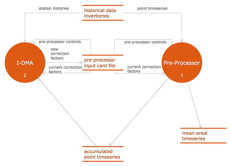
Accounting Information system is a combination of software and hardware, as well as organizational support. Information system - it is not only the software and computers with network equipment, but also a list of instructions and standards which can be notated using Accounting information systems flowchart symbols. All information systems can be divided into information retrieval and data processing systems. Data Flow model is a hierarchical model. Each process can be divided into structural components, that depict by corresponding flowchart symbols, showing the accounting information system in communication with the external environment. The major components of accounting information systems flowchart are: entities, processes, data stores, and data flows. The set of standard accounting information flowchart symbols is intended to show the relationships between the system components. ConceptDraw PRO can help to draw clear accounting information system diagrams using special flowchart symbols.
 Plumbing and Piping Plans
Plumbing and Piping Plans solution extends ConceptDraw PRO v10.2.2 software with samples, templates and libraries of pipes, plumbing, and valves design elements for developing of water and plumbing systems, and for drawing Plumbing plan, Piping plan, PVC Pipe plan, PVC Pipe furniture plan, Plumbing layout plan, Plumbing floor plan, Half pipe plans, Pipe bender plans.
The vector stencils library "Qualifying" contains 56 qualifying symbols of radiation, polarity, phase, windings, wire, ground, connection, connector, coaxial, electret.
Use these signs to annotate or specify characteristics of objects in electrical drawings, electronic schematics, circuit diagrams, electromechanical drawings, and wiring diagrams, cabling layout diagrams.
"An electrical drawing, is a type of technical drawing that shows information about power, lighting, and communication for an engineering or architectural project. Any electrical working drawing consists of "lines, symbols, dimensions, and notations to accurately convey an engineering's design to the workers, who install the electrical system on the job".
A complete set of working drawings for the average electrical system in large projects usually consists of:
(1) A plot plan showing the building's location and outside electrical wiring.
(2) Floor plans showing the location of electrical systems on every floor.
(3) Power-riser diagrams showing panel boards.
(4) Control wiring diagrams.
(5) Schedules and other information in combination with construction drawings.
Electrical drafters prepare wiring and layout diagrams used by workers who erect, install, and repair electrical equipment and wiring in communication centers, power plants, electrical distribution systems, and buildings." [Electrical drawing. Wikipedia]
The signs example "Design elements - Qualifying" was drawn using the ConceptDraw PRO diagramming and vector drawing software extended with the Electrical Engineering solution from the Engineering area of ConceptDraw Solution Park.
HelpDesk
Download and Install ConceptDraw Office on Mac
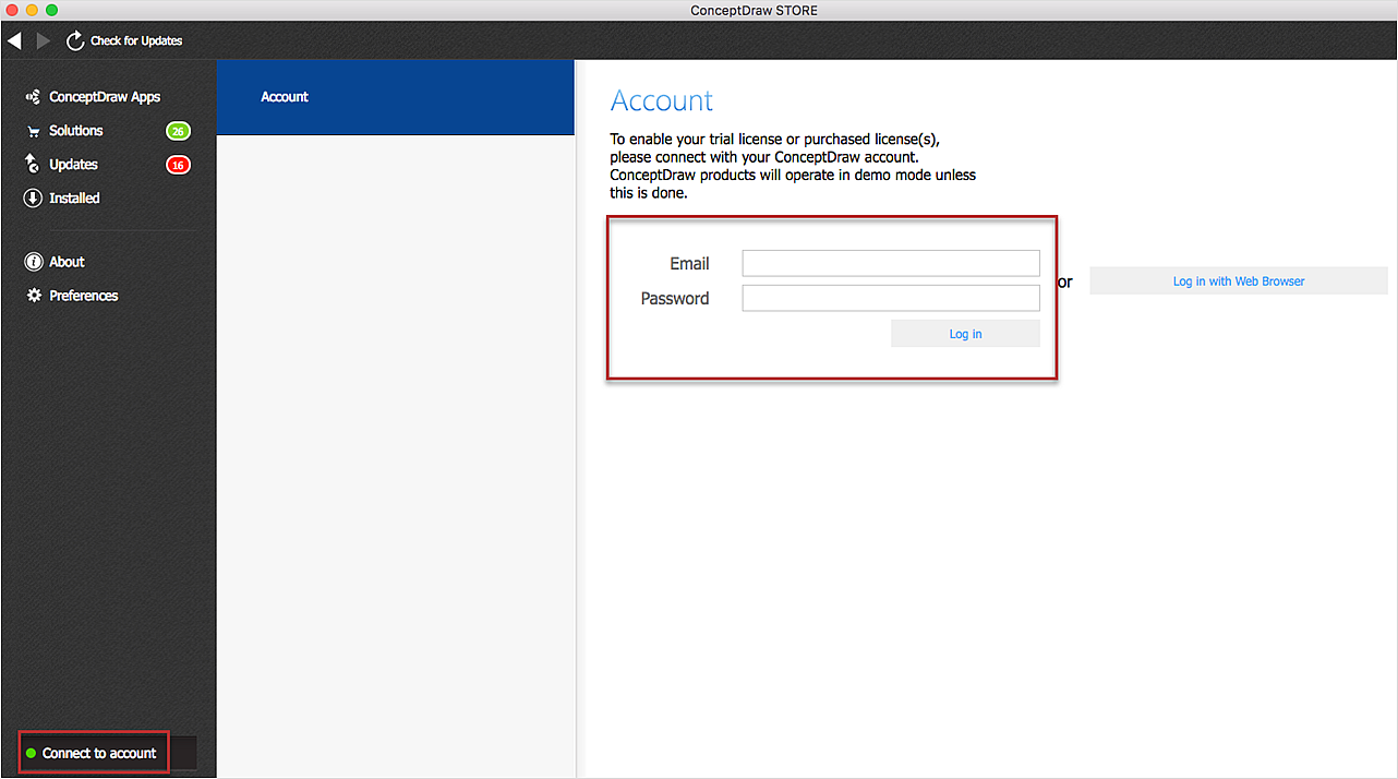
Find out how to download and install ConceptDraw software products for OS X on your computer. The download process is very simple due to the fact that all ConceptDraw applications are pooled into the ConceptDraw Office bundle. ConceptDraw STORE is a download manager that is responsible for downloading, installing, uninstalling and updating of the ConceptDraw Office for Windows and associated solutions.- Electrical Drawing Software | How To use House Electrical Plan ...
- Prepare The Symbol Of Engineering Of Electrical Instaletion
- Lighting and switch layout
- Drawing Symbols For Electrical Installation In Building
- Electrical Installation Symbols And Signs
- Electrical Control Panel Wiring Symbols Of Construction Line
- Electrical Wiring Symbols For Domestic And Industrial Installation
- How To use House Electrical Plan Software | Cafe electrical floor ...
- How To use House Electrical Plan Software | How To use Building ...
- Electrical Design And Installation Symbols
- Design elements - Qualifying | Fire Exit Plan. Building Plan ...
- How To use House Electrical Plan Software | How To Draw Building ...
- Drawing All Equipment Electrical For Install
- Electrical Installation Symbol
- Complete Design Of Distribution Board Of Electrical Drawing
- Drawing Electrical Symbols
- Example Of Architectural Building Electrical Installation
- Show A Duplex Ground Floor Plan With Electrical Installation Symbols
- Working Electrical Installation In Floor Plan How To
- Building Electrical Diagram Symbols


