Basic Flowchart Symbols and Meaning


Data Flow Diagram Symbols. DFD Library

Cloud Computing Architecture Diagrams

Restaurant Floor Plans Samples

Network Security Devices

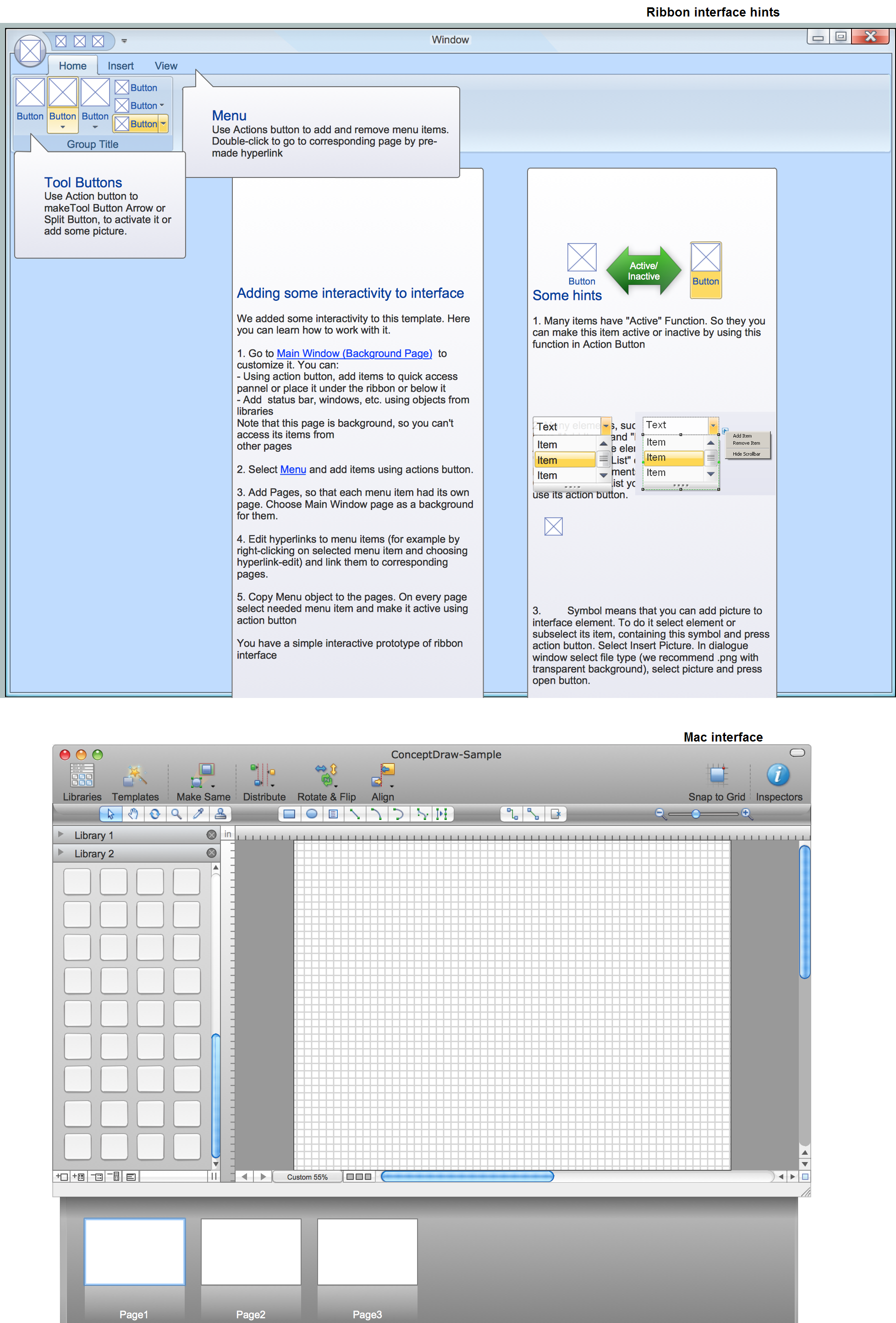
GUI Prototyping with ConceptDraw DIAGRAM
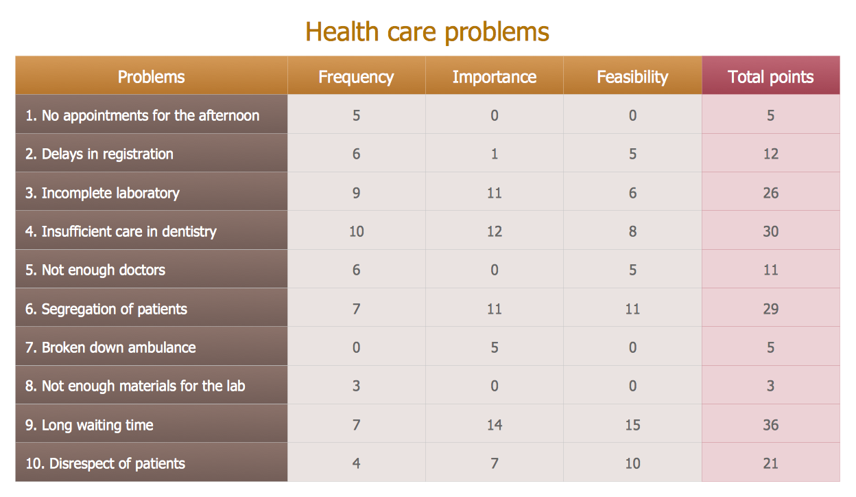
Prioritization Matrix
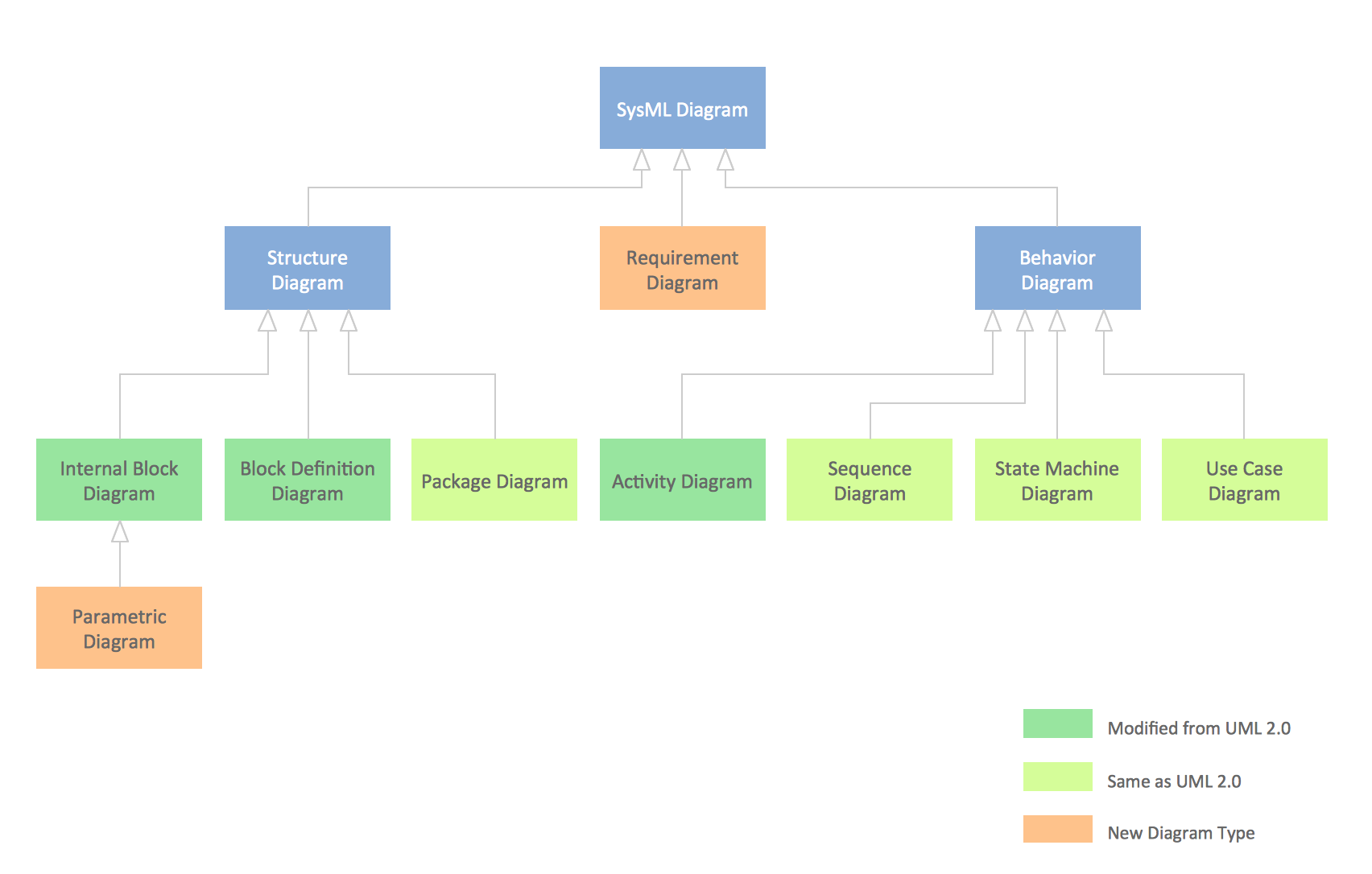
UML Diagram

 Interactive Voice Response Diagrams
Interactive Voice Response Diagrams solution extends ConceptDraw DIAGRAM software with samples, templates and libraries of ready-to-use vector stencils that help create Interactive Voice Response (IVR) diagrams illustrating in details a work of interactive voice response system, the IVR system’s logical and physical structure, Voice-over-Internet Protocol (VoIP) diagrams, and Action VoIP diagrams with representing voice actions on them, to visualize how the computers interact with callers through voice recognition and dual-tone multi-frequency signaling (DTMF) keypad inputs.
SysML Diagram
- Flowchart Showing How We Process Sound
- Sound System Flowchart
- Different Types Sound Systems Diagram
- Bubble Chart On Types Of Sound
- Prepare Flow Chart Of Sound Symbols Images
- Preparation Flow Chart Of Sound Symbols
- How To Make Sound Sistem
- Basic Flowchart Symbols and Meaning | How To use House ...
- How To use House Plan Software | Basic Flowchart Symbols and ...