Network Security

Network Glossary Definition


Local area network (LAN). Computer and Network Examples
 diagram")
Cisco Routers. Cisco icons, shapes, stencils and symbols

Home area networks (HAN). Computer and Network Examples

Network Diagram Software. LAN Network Diagrams. Physical Office Network Diagrams

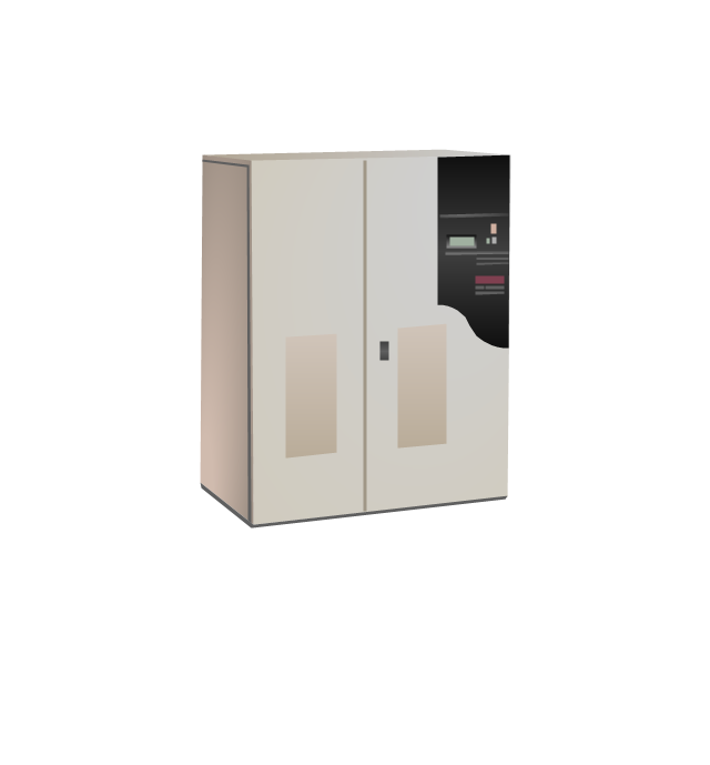
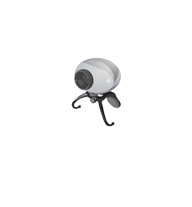
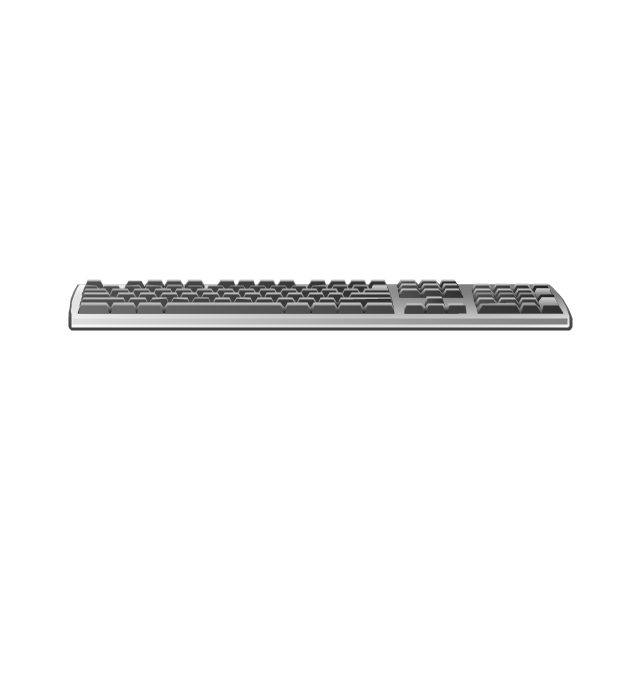
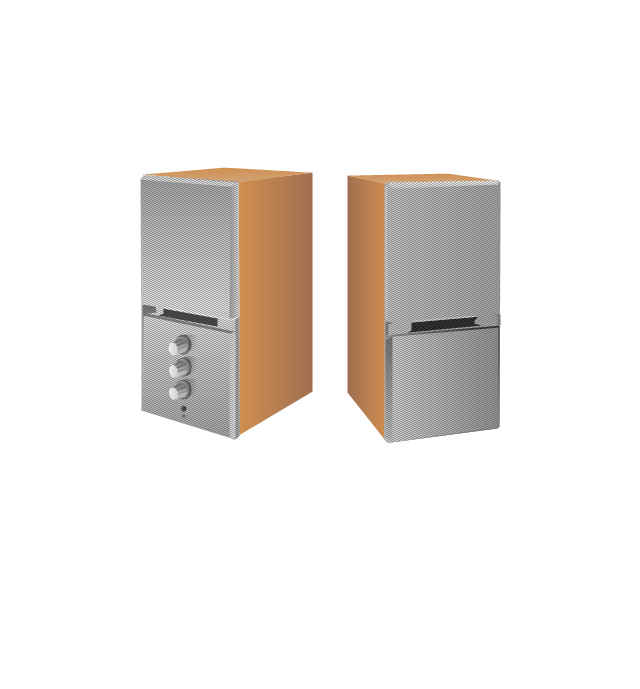
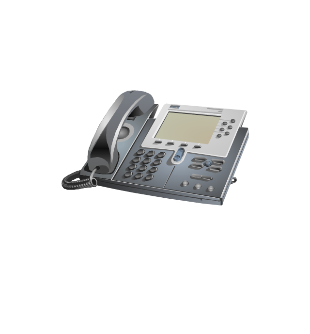
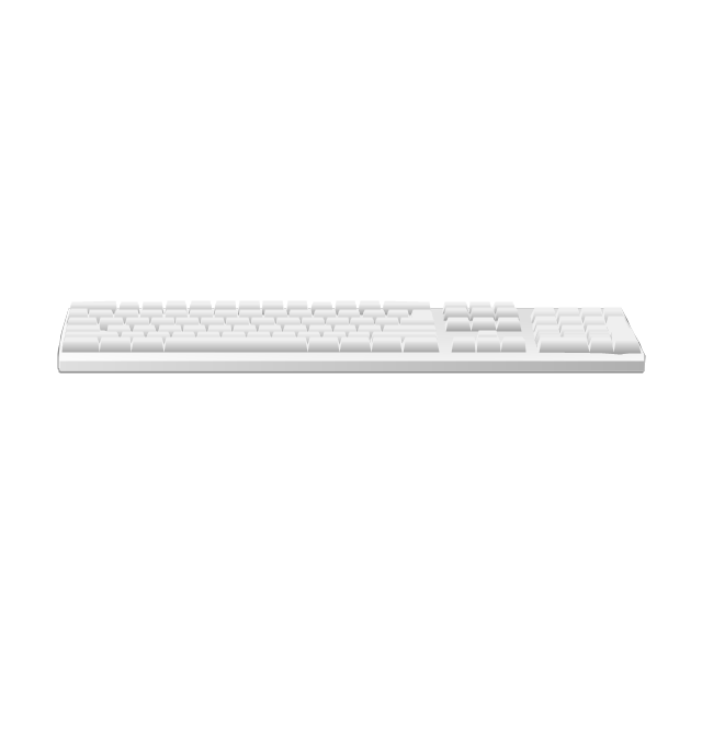
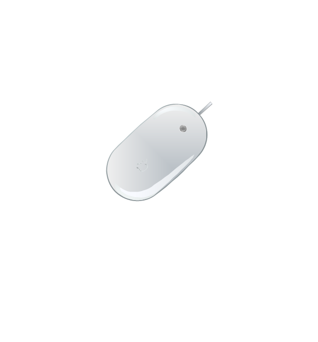
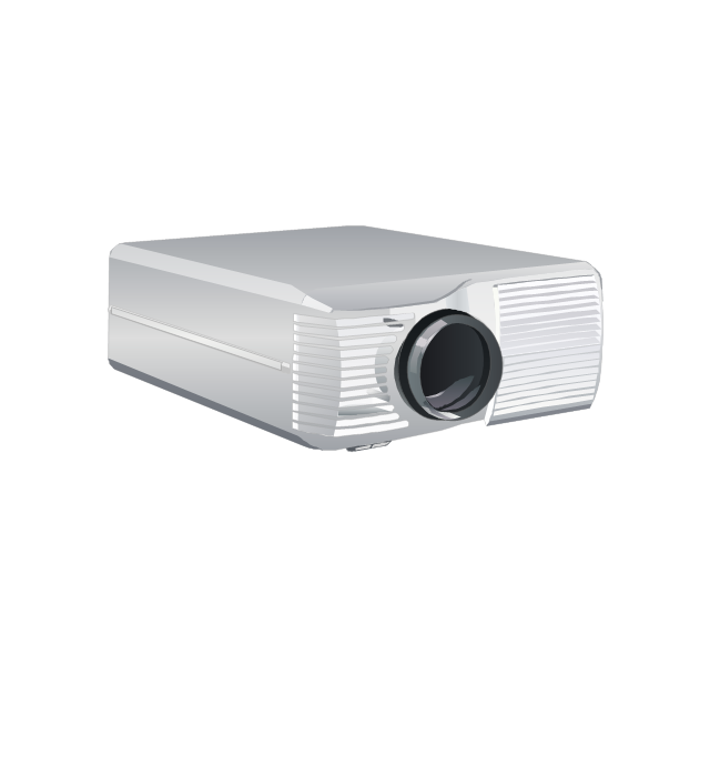
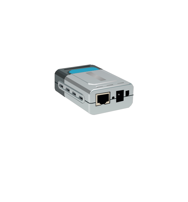
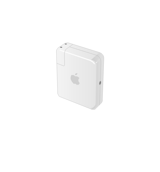
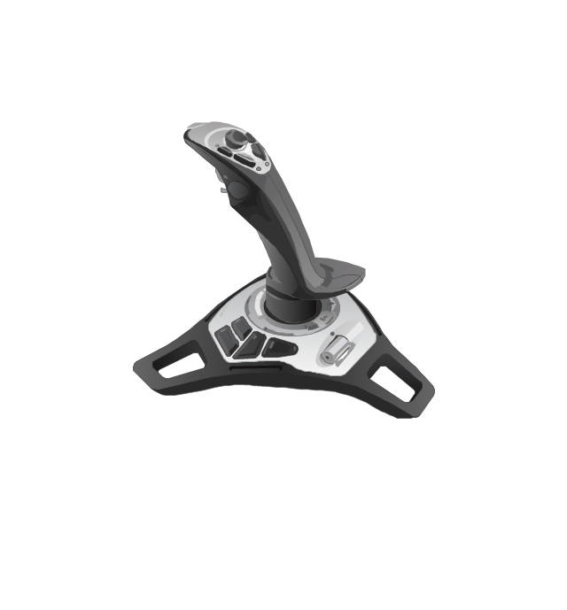
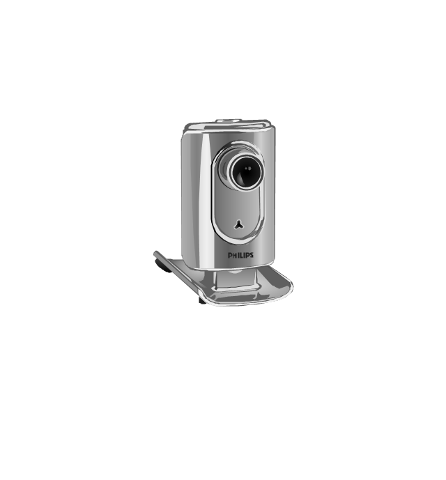
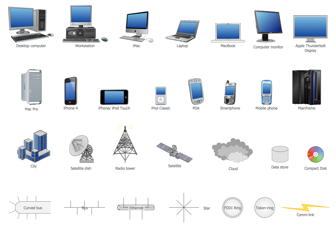
The vector stencils library "Computer peripheral devices" contains 18 clipart images of computer peripheral devices and equipment for drawing network diagrams.
"A peripheral is a device that is connected to a host computer, but not an integral part of it. It expands the host's capabilities but does not form part of the core computer architecture. It is often, but not always, partially or completely dependent on the host.
There are three different types of peripherals:
(1) Input, used to interact with, or send data to the computer (mouse, keyboards, etc.).
(2) Output, which provides output to the user from the computer (monitors, printers, etc.).
(3) Storage, which stores data processed by the computer (hard drives, flash drives, etc.)" [Peripheral. Wikipedia]
The clip art example "Computer peripheral devices - Vector stencils library" was created using the ConceptDraw PRO diagramming and vector drawing software extended with the Computer and Networks solution from the Computer and Networks area of ConceptDraw Solution Park.
Uninterruptible power supply
Webcam
Keyboard
Optical mouse

Computer speakers
Headphones

VoIP phone
Apple Keyboard
Apple Mouse
LCD projector
Port adapter
Airport Express
Joystick
Webcam
Video projector
 Computer and Networks Area
The solutions from Computer and Networks Area of ConceptDraw Solution Park collect samples, templates and vector stencils libraries for drawing computer and network diagrams, schemes and technical drawings.
Network Icon
 Computer Network Diagrams
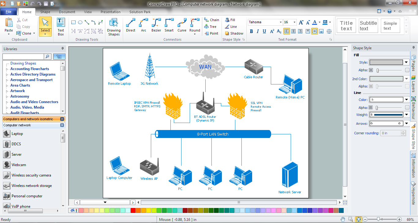
Computer Network Diagrams solution extends ConceptDraw DIAGRAM software with samples, templates and libraries of vector icons and objects of computer network devices and network components to help you create professional-looking Computer Network Diagrams, to plan simple home networks and complex computer network configurations for large buildings, to represent their schemes in a comprehensible graphical view, to document computer networks configurations, to depict the interactions between network's components, the used protocols and topologies, to represent physical and logical network structures, to compare visually different topologies and to depict their combinations, to represent in details the network structure with help of schemes, to study and analyze the network configurations, to communicate effectively to engineers, stakeholders and end-users, to track network working and troubleshoot, if necessary.
Block Diagram

Network Icons
UML Component Diagram. Design Elements


How to Build Cloud Computing Diagram Principal Cloud Manufacturing

This pinout diagram example showing a VGA connector (as viewed from the socket) was redesigned from the Wikimedia Commons file: DE15 Connector Pinout.svg. [commons.wikimedia.org/ wiki/ File:DE15_ Connector_ Pinout.svg]
"A Video Graphics Array (VGA) connector is a three-row 15-pin DE-15 connector. The 15-pin VGA connector is found on many video cards, computer monitors, and high definition television sets. On laptop computers or other small devices, a mini-VGA port is sometimes used in place of the full-sized VGA connector.
DE-15 is also conventionally called RGB connector, D-sub 15, mini sub D15, mini D15, DB-15, HDB-15, HD-15 or HD15 (High Density, to distinguish it from the older and less flexible DE-9 connector used on some older VGA cards, which has the same shell size but only two rows of pins).
VGA connectors and cables carry analog component RGBHV (red, green, blue, horizontal sync, vertical sync) video signals, and VESA Display Data Channel (VESA DDC) data. In the original version of DE-15 pinout, one pin was keyed by plugging the female connector hole; this prevented non-VGA 15 pin cables from being plugged into a VGA socket. Four pins carried Monitor ID bits which were rarely used; VESA DDC redefined some of these pins and replaced the key pin with +5 V DC power supply.
The VGA interface is not engineered to be hotpluggable (so that the user can connect or disconnect the output device while the host is running), although in practice this can be done and usually does not cause damage to the hardware or other problems. However, nothing in the design ensures that the ground pins make a connection first and break last, so hotplugging may introduce surges in signal lines which may or may not be adequately protected against. Also, depending on the hardware and software, detecting a monitor being connected might not work properly in all cases." [VGA connector. Wikipedia]
The pinout diagram example "VGA connector pinout" was created using the ConceptDraw PRO diagramming and vector drawing software extended with the Audio and Video Connectors solution from the Engineering area of ConceptDraw Solution Park.
VGA connector pinout

- Design elements - Hardware | Computer Desktop Sockets And Ports ...
- Server hardware - Rack diagram | Hardware - Vector stencils library ...
- Computer peripheral devices - Vector stencils library | Design ...
- Laptop Port Icons
- Local area network (LAN). Computer and Network Examples ...
- Computer pictograms - Vector stencils library | Computer peripheral ...
- Computer Hardware And Software Cliparts
- Local area network (LAN). Computer and Network Examples ...
- Computer peripheral devices - Vector stencils library | Dynamic ...
- Floor Plan With Computer Networks
- Computer peripheral devices - Vector stencils library | Computer ...
- Hardware - Vector stencils library | Computers and network isometric ...
- Network Layout Floor Plans | Local area network (LAN). Computer ...
- Computer network - Vector stencils library | Hardware - Vector ...
- HVAC controls - Vector stencils library | Hardware - Vector stencils ...
- How to Draw a Computer Network Diagrams | Personal area (PAN ...
- Computer peripheral devices - Vector stencils library | Wide area ...
- Hardware - Vector stencils library | Hardware - Vector stencils library ...
- Network hardware - Vector stencils library | Hardware - Vector ...
- Local area network (LAN). Computer and Network Examples | How ...