Metropolitan area networks (MAN). Computer and Network Examples
. Computer and Network Examples")

Campus Area Networks (CAN). Computer and Network Examples
. <br>Computer and Network Examples *")
Entity Relationship Diagram Symbols

Local area network (LAN). Computer and Network Examples
 diagram")
Cloud Computing Architecture Diagrams

How to Draw a Computer Network Diagrams

Network Community Structure. Computer and Network Examples

Cisco Routers. Cisco icons, shapes, stencils and symbols

The vector stencils library "Computers and network isometric" contains 56 3D clipart images of computer and network devices and equipment for drawing network diagrams.
The clip art example "Computers and network isometric - Vector stencils library" was created using the ConceptDraw PRO diagramming and vector drawing software extended with the Computer and Networks solution from the Computer and Networks area of ConceptDraw Solution Park.
The clip art example "Computers and network isometric - Vector stencils library" was created using the ConceptDraw PRO diagramming and vector drawing software extended with the Computer and Networks solution from the Computer and Networks area of ConceptDraw Solution Park.
Laptop

DDCS

Server

Webcam

Wireless Network Storage

Personal computer

VoIP phone

Fax

Plotter

Mobile phone

Feature phone

Printer

Satellite dish

Satellite antenna

Automatic-tracking satellite dish
Wireless access point

Wireless router

Router

Network switch

Network device

Mobile GPS Terminal

GPS phone

Television antenna

Radio tower

Base station

Satellite

In-vehicle satellite telecommunication

Satellite dishes on ship

Airplane

Internet

Man

Woman

Call-center

Honeycomb

Mountain

Radio waves

Radio waves

Tower block

Office building

House

House

Globe

Wireless security camera

Truck

Tree

Conifer tree

1U hub / switch

2U hub / switch

1U server

2U Server

3U Server

4U Server

Communications satellite

Car

Radio waves

Firewall

Guesthouse Network. WIFI network to my guest house

Guesthouse Network. WIFI network to my guest house
Example of DFD for Online Store (Data Flow Diagram)


Calculate the cost of creating or updating a wireless computer network

Server

Using Both Wired and Wireless Connections

 Network Security Diagrams
The Network Security Diagrams solution presents a large collection of predesigned cybersecurity vector stencils, cliparts, shapes, icons and connectors to help you succeed in designing professional and accurate Network Security Diagrams, Network Security Infographics to share knowledge about effective ways of networks protection with help of software and network security devices of different cyber security degrees, Network Plans for secure wireless network, Computer Security Diagrams to visually tell about amazing possibilities of IT security solutions. The samples and examples reflect the power of ConceptDraw DIAGRAM software in drawing Network Security Diagrams, give the representation about variety of existing types of attacks and threats, help to realize their seriousness and the methods to deal with them.
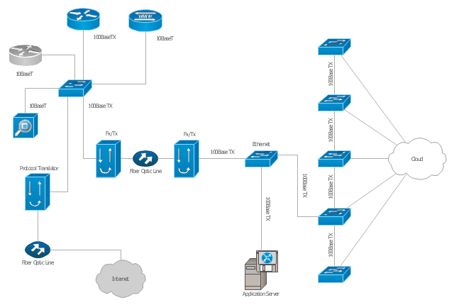
"A computer network diagram is a schematic depicting the nodes and connections amongst nodes in a computer network or, more generally, any telecommunications network. ...
Depending on whether the diagram is intended for formal or informal use, certain details may be lacking and must be determined from context. ...
At different scales diagrams may represent various levels of network granularity. At the LAN level, individual nodes may represent individual physical devices, such as hubs or file servers, while at the WAN level, individual nodes may represent entire cities. In addition, when the scope of a diagram crosses the common LAN/ MAN/ WAN boundaries, representative hypothetical devices may be depicted instead of showing all actually existing nodes." [Computer network diagram. Wikipedia]
The Cisco computer network diagram example "Network organization chart" was created using the ConceptDraw PRO diagramming and vector drawing software extended with the Cisco Network Diagrams solution from the Computer and Networks area of ConceptDraw Solution Park.
Cisco network diagram
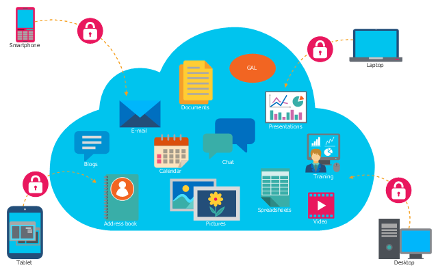
This cloud computing infographic example was drawn on the base of Wikimedia Commons file: Cloud applications SVG.svg. [commons.wikimedia.org/ wiki/ File:Cloud_ applications_ SVG.svg]
This file is made available under the Creative Commons CC0 1.0 Universal Public Domain Dedication. [creativecommons.org/ publicdomain/ zero/ 1.0/ deed.en]
"Cloud computing is a model for enabling ubiquitous, convenient, on-demand network access to a shared pool of configurable computing resources (e.g., networks, servers, storage, applications and services) that can be rapidly provisioned and released with minimal management effort." [Cloud computing. Wikipedia]
The cloud computing infographic example "Cloud applications" was drawn using ConceptDraw PRO software extended with the Cloud Computing Diagrams solution from the Computer and Networks area of ConceptDraw Solution Park.
Cloud computing infographic
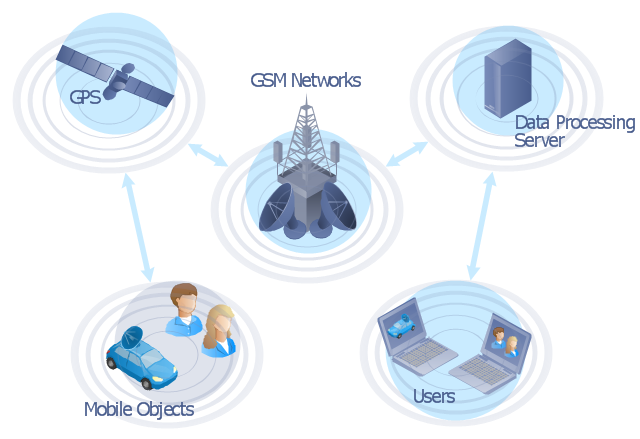
"The Global Positioning System (GPS) is a space-based satellite navigation system that provides location and time information in all weather conditions, anywhere on or near the Earth where there is an unobstructed line of sight to four or more GPS satellites. The system provides critical capabilities to military, civil and commercial users around the world. It is maintained by the United States government and is freely accessible to anyone with a GPS receiver." [Global Positioning System. Wikipedia]
This GPS operation diagram example was created using the ConceptDraw PRO diagramming and vector drawing software extended with the Telecommunication Network Diagrams solution from the Computer and Networks area of ConceptDraw Solution Park.
This GPS operation diagram example was created using the ConceptDraw PRO diagramming and vector drawing software extended with the Telecommunication Network Diagrams solution from the Computer and Networks area of ConceptDraw Solution Park.
GPS network diagram
Onion Diagram Process Design

- Network organization chart | Model Based On Lan Man Wan
- Model Based On Lan Wan Man
- Cardboard Computer Model Based On Lan Man Wan
- Local area network (LAN). Computer and Network Examples ...
- Make A Model On Lan Man Wan
- Hybrid Network Topology | Lan Man Wan Thermocol Project
- Network Diagram Examples | Wide area network (WAN) topology ...
- How To Make 3d Model Of Lan And Wan
- Local area network (LAN). Computer and Network Examples ...
- Local area network (LAN). Computer and Network Examples ...
- Local area network (LAN). Computer and Network Examples | Wide ...
- Local area network (LAN). Computer and Network Examples ...
- Structure Of Lan Wan Man
- Metropolitan area networks ( MAN ). Computer and Network Examples
- Metropolitan area networks ( MAN ). Computer and Network Examples
- Create A Thermocol Model To Show The Working Of Internet By ...
- Model Of Lan Man Wan
- Process Flowchart | Metropolitan area networks ( MAN ). Computer ...
- Metropolitan area networks ( MAN ). Computer and Network ...
- Local area network (LAN). Computer and Network Examples ...