Hybrid Network Topology

Hotel Network Topology
Wireless Network Topology

Cisco Network Diagram Software

Cisco Network Topology. Cisco icons, shapes, stencils and symbols

Bus Network Topology

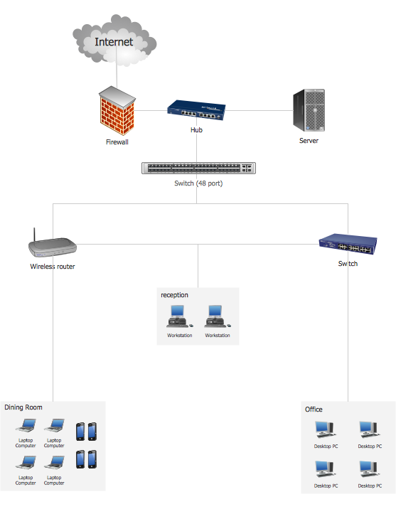
 Computer Network Diagrams
Computer Network Diagrams solution extends ConceptDraw DIAGRAM software with samples, templates and libraries of vector icons and objects of computer network devices and network components to help you create professional-looking Computer Network Diagrams, to plan simple home networks and complex computer network configurations for large buildings, to represent their schemes in a comprehensible graphical view, to document computer networks configurations, to depict the interactions between network's components, the used protocols and topologies, to represent physical and logical network structures, to compare visually different topologies and to depict their combinations, to represent in details the network structure with help of schemes, to study and analyze the network configurations, to communicate effectively to engineers, stakeholders and end-users, to track network working and troubleshoot, if necessary.
Fully Connected Network Topology Diagram

Complete Network Topology

Network Topology Mapper

- Types Of Network Topology Ppt
- Presentation On Network Topology
- Network Topology Ppt Presentation Free Download
- Powerpoint Backgrounds Computer Network
- Metropolitan Area Network Ppt Free Download
- Hybrid Network Topology | Wireless Network Topology | Daisy ...
- How To Add a Computer Network Diagram to a PowerPoint ...
- Powerpoint Presentation On Computer Networking
- Prepare A Power Point Presentation About Computer Network
- How To Add a Computer Network Diagram to a PowerPoint ...