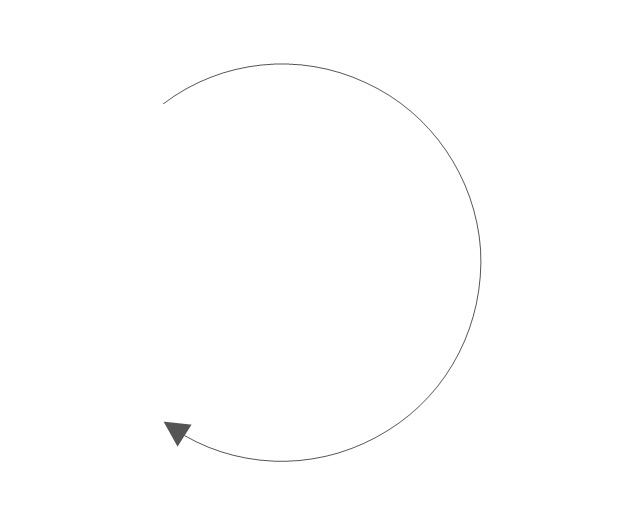
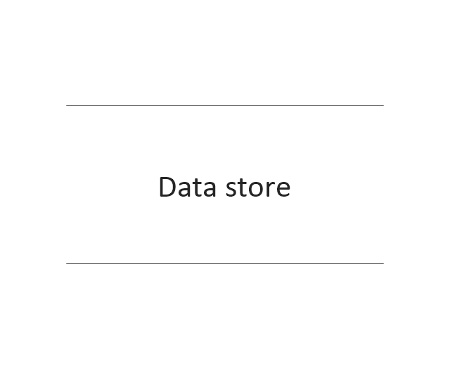
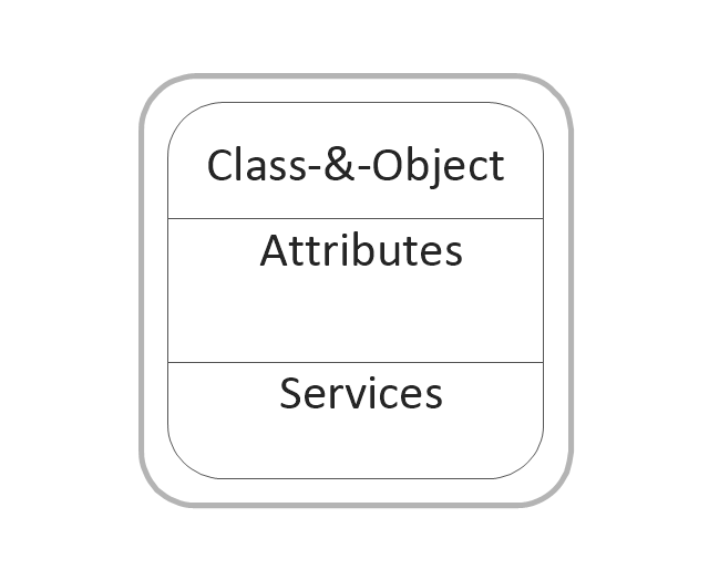
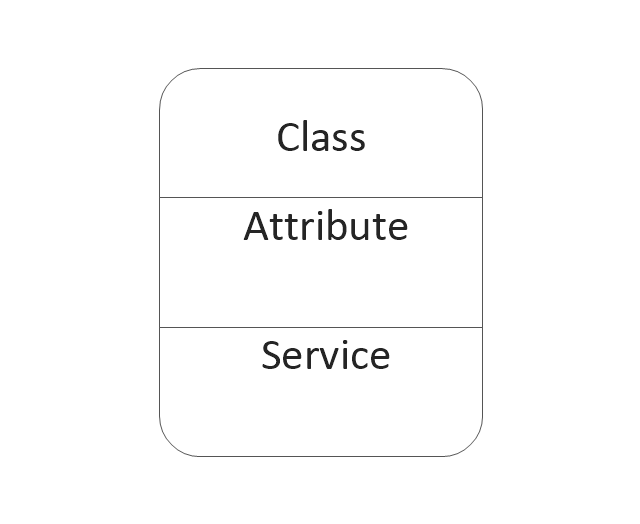
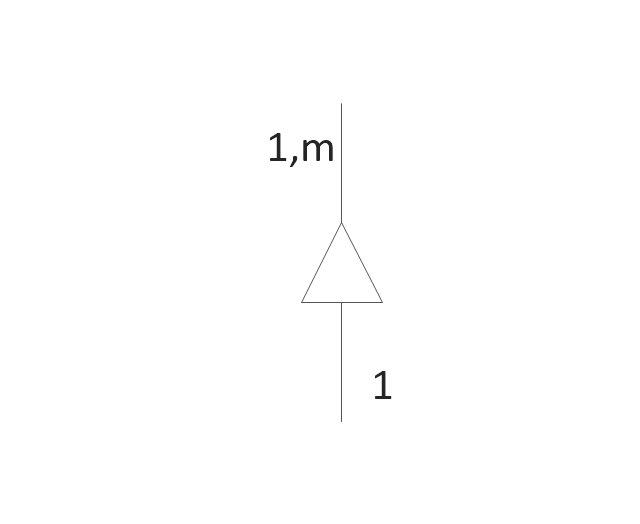
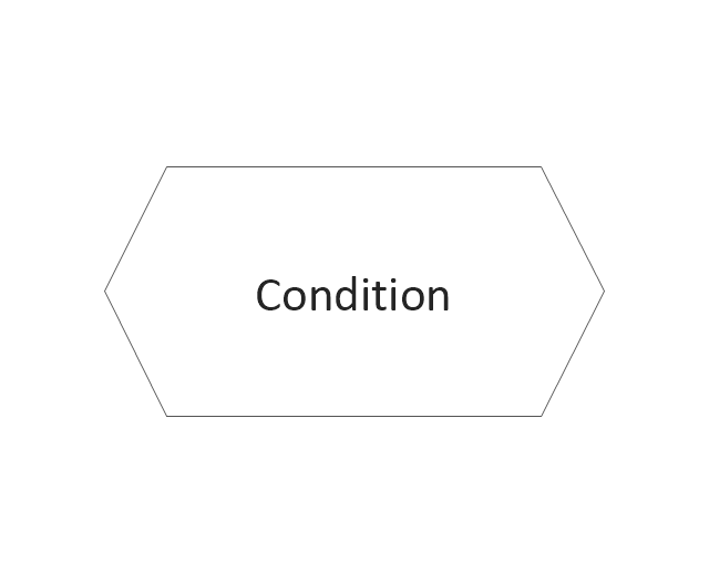
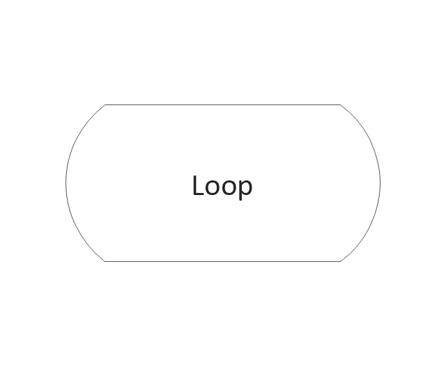
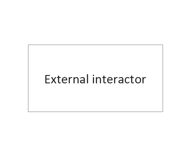
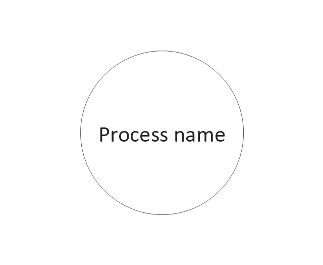
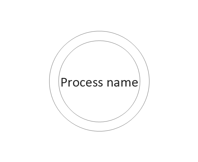
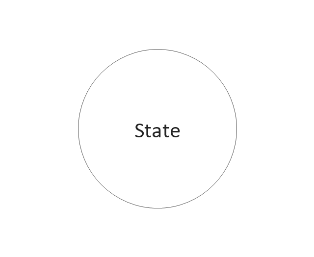
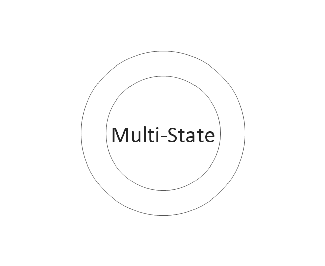
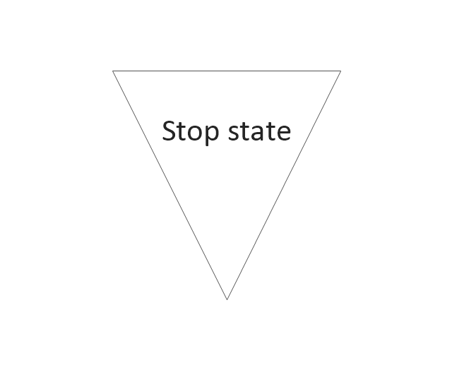
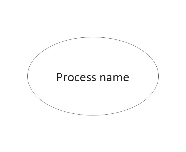
The vector stencils library "DFD, Yourdon and Coad notation" contains 22 DFD elements.
Use it for drawing data flow diagrams (DFD) using Yourdon/ DeMarco notation in the ConceptDraw PRO diagramming and vector drawing software extended with the Data Flow Diagrams solution from the Software Development area of ConceptDraw Solution Park.
Use it for drawing data flow diagrams (DFD) using Yourdon/ DeMarco notation in the ConceptDraw PRO diagramming and vector drawing software extended with the Data Flow Diagrams solution from the Software Development area of ConceptDraw Solution Park.
Design Data Flow. DFD Library
Data flow diagram or DFD is a type of diagrams used for graphical representation the "flow" of data through an information system, for effective modeling its process aspects and for visualization the data processing. They are one of the best tools for clearly making an overview of the system that will be developed, for depiction in details what kinds of information will be inputted to the system and outputted from it, where they will be stored, and other details. ConceptDraw PRO software with Data Flow Diagrams solution from Software Development area of ConceptDraw Solution Park is powerful in a field of designing the DFDs. Three libraries containing 49 vector DFD shapes and symbols are offered by Data Flow Diagrams (DFD) solution. Use them to design data flow diagrams, information flow diagrams, data flowcharts, data process diagrams, structured analysis diagrams, to create the data-oriented models or process-oriented models, and so on. Pay also attention for the included collection of DFD samples, examples and built-in templates at ConceptDraw STORE.Basic Flowchart Symbols and Meaning
Flowcharts are the best for visually representation the business processes and the flow of a custom-order process through various departments within an organization. ConceptDraw PRO diagramming and vector drawing software extended with Flowcharts solution offers the full set of predesigned basic flowchart symbols which are gathered at two libraries: Flowchart and Flowcharts Rapid Draw. Among them are: process, terminator, decision, data, document, display, manual loop, and many other specific symbols. The meaning for each symbol offered by ConceptDraw gives the presentation about their proposed use in professional Flowcharts for business and technical processes, software algorithms, well-developed structures of web sites, Workflow diagrams, Process flow diagram and correlation in developing on-line instructional projects or business process system. Use of ready flow chart symbols in diagrams is incredibly useful - you need simply drag desired from the libraries to your document and arrange them in required order. There are a few serious alternatives to Visio for Mac, one of them is ConceptDraw PRO. It is one of the main contender with the most similar features and capabilities.
DFD Library — Design elements
Data Flow Diagrams (DFD) solution from the Software Development area of ConceptDraw Solution Park provides plenty of predesigned templates, samples and DFD vector design elements proposed by three DFD libraries. These DFD library objects are designed to help you effectively model the data flows and functional requirements for the business processes or systems, to design the Process-oriented models or Data-oriented models, Data flowcharts and Data process diagrams, Structured analysis diagrams and Information flow diagrams. There are two different notations used to draw the Data Flow Diagrams (Yourdon & Coad and Gane & Sarson). These notations define the different visual representations for the processes, data stores, data flows, and external entities. ConceptDraw PRO software provides you with possibility of designing professional-looking Data Flow Diagrams, DFD Models, Data Flow Process Diagrams using any of these notations. Simply drag the predesigned DFD flowchart symbols from the appropriate library and connect by arrows depicting the data flow from one step to another.Data Flow Diagram (DFD)
A Data Flow Diagram (DFD) illustrates the flow of data through an information system, visualizes how the information is handled in terms of inputs and outputs, how the data enter to system and leave it. It is effective to use a Data Flow Diagram for creation the system's overview, to show the system's scope and boundaries. There are two different types of notations for DFDs: Yourdon-Coad and Gane-Sarson, which differ in visual representations for processes, data flow, data stores, external entities, etc. Thus, for example the processes are depicted as circles in Yourdon-Coad notation and as rounded squares in Gane-Sarson notation. Gane-Sarson notation is usually used for visualization information systems and Yourdon-Coad - for system analysis and design. The Data Flow Diagrams solution included to Software Development area of ConceptDraw Solution Park offers a lot of DFD templates, samples and examples, libraries of vector stencils for construction without efforts the DFDs according to both Gane-Sarson and Yourdon-Coad notations.Flowchart
The Flowcharts are widespread in various fields and include the multitude of types. They are dedicated to representation the algorithms, processes, workflows of any complexity in a clear and intuitive format. The Flowcharts are commonly used in software development as a visual tool for illustration algorithms and logic of computer programs, in business for illustration business scenarios, in education, and so on. For drawing the Flowchart are used the special object blocks, among them rectangle or box used to represent an activity or step, rounded box or oval to depict Start / End, diamond to represent the decision point (involves the branching yes/no), circle used to represent the point of connection, parallelogram to represent the Input / Output, and some others. With ConceptDraw PRO including Flowcharts solution it is easy to create professional-looking Flowchart diagrams of any complexity and any degree of detailing. Succeed in drawing the Flowcharts using quick-start templates, predesigned samples and extensive libraries of ready-made flowchart symbols, blocks and icons.How to Connect Social Media DFD Flowchart with Action Maps
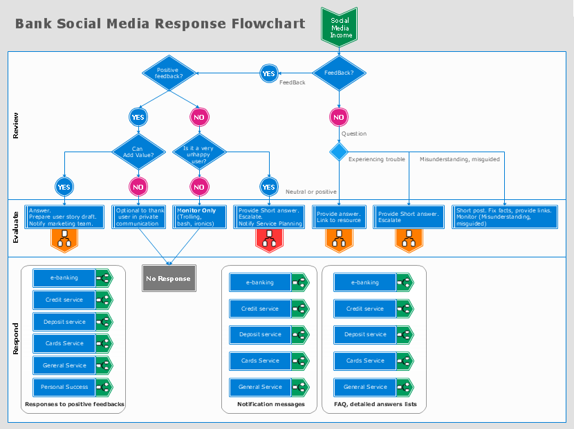
The Social Media Response solution creates interactive social media flow charts and action mind maps. The solution includes a video tutorial and a number of samples helping social media teams refine and organize their response process.Flow Chart Creator
ConceptDraw PRO is a flowchart design software. There are large collections of professional flowchart symbols for process flow diagrams, standard flowchart symbols and colored basic flowchart symbols. Built-in examples and video lessons allow users to get started immediately and do drawing of virtually any type of flowchart or process flow diagramsIDEF4 Standard
Use Case Diagrams technology. IDEF4 standard implies not only graphical presentation but the additional information about diagrams of heredity, methods systematization and types which are contained in specifications.Easy Flowchart Program and Standard Flowchart Symbols
Fast visualization of structured data is main capability of the ConceptDraw PRO. With numerous vector stencils and standard flowchart symbols from object libraries and the RapidDraw technology this program stands as the best professional flowchart software for drawing with type of flowchart symbols. ConceptDraw PRO also known as best flowchart maker.Garrett IA Diagrams with ConceptDraw PRO
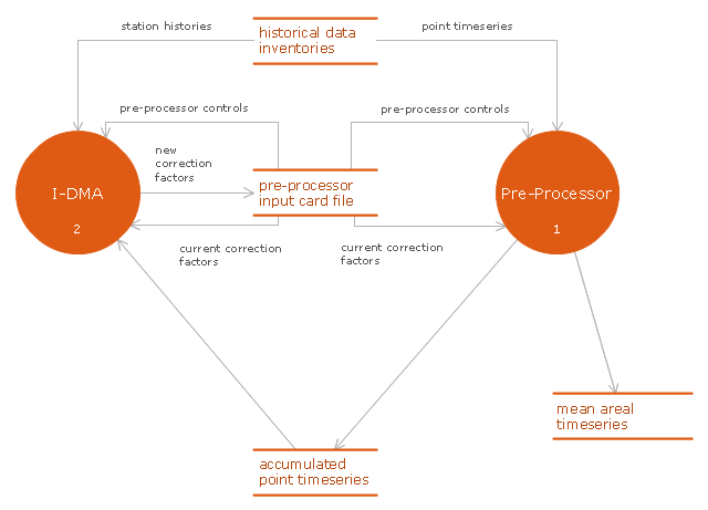
Garrett IA diagrams are used at development of Internet-resources, in particulars at projecting of interactions of web-resource elements. The diagram of information architecture of the web resource which is constructed correctly with necessary details presents to developers the resource in comprehensible and visual way.This DFD sample was created on the base of figure illustrating the "Interactive Double Mass Analysis. User's Guide" from the website of the Office of Hydrologic Development of the National Weather Service (NWS) of the National Oceanic and Atmospheric Administration (NOAA).
"Double mass analysis is a technique commonly employed to determine corrections to hydrometeorological data to account for changes in data collection procedures or other local conditions. The changes may result from a variety of things including changes in instrumentation, changes in observation procedures, or changes in gage location or surrounding conditions. The purpose of this Interactive Double Mass Analysis (IDMA) tool is to provide an effective and efficient way for users to perform consistency checking using double mass analysis and to produce the correction factors that are used in subsequent processing by NWSRFS preprocessor tools to account for any discovered inconsistencies.
Computations of mean areal time series for use in calibration and ESP have traditionally been made using the appropriate preprocessing software (MAP, PXPP, MAT etc.). The preprocessors have traditionally taken point time series as input and have provided facilities for estimation of missing data, and for consistency checking and correction in addition to the mean areal computations. The IDMA tool has been designed to run in conjunction with the preprocessors in an iterative fashion. It performs the consistency checking function, leaving the estimation, correction and mean areal computations to the preprocessors. ...
As shown in Figure ... the preprocessor software generates a data file that contains accumulated data values for each station and the associated group base, as well as flags indicating whether the values were estimated or not. This data file along with the input card file used by the preprocessor are used by the IDMA tool. The IDMA tool then allows the user to perform consistency checks and to calculate correction factors. The correction factors are then returned so that the preprocessors can perform the corrections, re-estimate missing data and perform the mean areal computations. Note that there is an interdependence between the estimation of missing values in the preprocessors and the correction factors computed in the IDMA and so there needs to be iteration between the two processes until the user is satisfied that an appropriate balance has been reached."
[nws.noaa.gov/ oh/ hrl/ idma/ users_ guide/ html/ dma_ overview.php]
The example "Interaction between IDMA and preprocessor" was created using the ConceptDraw PRO diagramming and vector drawing software extended with the Data Flow Diagrams solution from the Software Development area of ConceptDraw Solution Park.
Cross-Functional Flowchart
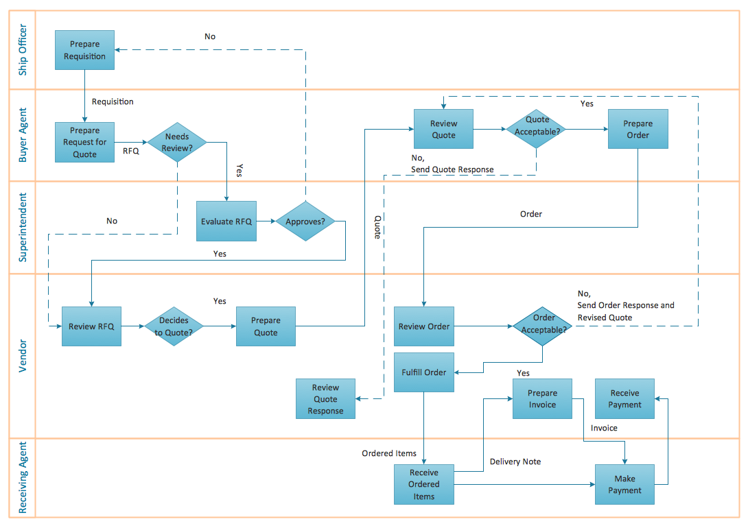
Use of Cross-Functional Flowchart is a clear way of showing each team member’s responsibilities and how processes get shared or transferred between different responsible people, teams and departments. Use the best flowchart maker ConceptDraw PRO with a range of standardized cross-functional flowchart symbols to create the Cross-Functional Flowcharts simply and to visualize the relationship between a business process and the functional units responsible for that process. To draw the most quickly Cross-Functional Flowcharts, Cross Functional Process Maps, or Cross Functional Process Flow Diagrams, start with a Cross-functional flowchart samples and templates from ConceptDraw Solution Park. The ConceptDraw Arrows10 and RapidDraw technologies will be also useful for you in drawing. ConceptDraw PRO supports designing both types - horizontal and vertical Cross-functional flowcharts. A vertical layout makes the accents mainly on the functional units while a horizontal layout - on the process. If you need a Visio alternative in Mac OS X, try ConceptDraw PRO. Its interface is very intuitive and it’s actually much easier to use than Visio, yet somehow it’s just as powerful if not more so. ConceptDraw PRO performs professional quality work and seamless Visio interaction.
- Process Flowchart | Data Flow Diagram | How to Create Flowcharts ...
- DFD , Yourdon and Coad notation - Vector stencils library
- Design Data Flow. DFD Library | DFD , Yourdon and Coad notation ...
- DFD , Yourdon and Coad notation - Vector stencils library | DFD ...
- DFD , Yourdon and Coad notation - Vector stencils library | Data ...
- Yourdon and Coad Diagram | DFD , Yourdon and Coad notation ...
- Yourdon and Coad Diagram | Coad/Yourdon's Object-Oriented ...
- DFD , Yourdon and Coad notation - Template | Yourdon and Coad ...
- Data Flow Diagram Symbols. DFD Library | DFD , Yourdon and Coad ...
- DFD , Yourdon and Coad notation - Template
- DFD Library System | DFD Library - Design elements | Data Flow ...
- Design Data Flow. DFD Library | Data Flow Diagram Process | DFD ...
- How can you illustrate the weather condition | Affinity diagram ...
- Yourdon and Coad Diagram | DFD Library - Design elements ...
- Business Tools Perceptual Mapping | How to Create a Social Media ...
- Process Flow Chart Symbols | How can you illustrate the weather ...
- UML Sequence Diagram. Design Elements | Design Data Flow. DFD ...
- Yourdon and Coad Diagram | DFD Library - Design elements | Data ...
- Data flow Model Diagram | Data Flow Diagram Model | Structured ...
- Data Flow Diagram Symbols. DFD Library | DFD Library - Design ...


-dfd,-yourdon-and-coad-notation---vector-stencils-library.png--diagram-flowchart-example.png)
