HelpDesk
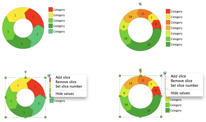
How to Draw the Different Types of Pie Charts
Using the Pie Chart, you can visually estimate the relative contribution that different data categories contribute to a whole value. The pie chart displays the statistics in a visual format. The main use of pie charts to show comparisons. The larger piece of the pie, the more the value of this value compared to the rest. Various applications of pie charts can be found in business and education. For business, pie charts can be used to compare the success or failure of the goods or services. They may also be used to display the business market share.The vector stencils library "Qualifying" contains 56 qualifying symbols of radiation, polarity, phase, windings, wire, ground, connection, connector, coaxial, electret.
Use these signs to annotate or specify characteristics of objects in electrical drawings, electronic schematics, circuit diagrams, electromechanical drawings, and wiring diagrams, cabling layout diagrams.
"An electrical drawing, is a type of technical drawing that shows information about power, lighting, and communication for an engineering or architectural project. Any electrical working drawing consists of "lines, symbols, dimensions, and notations to accurately convey an engineering's design to the workers, who install the electrical system on the job".
A complete set of working drawings for the average electrical system in large projects usually consists of:
(1) A plot plan showing the building's location and outside electrical wiring.
(2) Floor plans showing the location of electrical systems on every floor.
(3) Power-riser diagrams showing panel boards.
(4) Control wiring diagrams.
(5) Schedules and other information in combination with construction drawings.
Electrical drafters prepare wiring and layout diagrams used by workers who erect, install, and repair electrical equipment and wiring in communication centers, power plants, electrical distribution systems, and buildings." [Electrical drawing. Wikipedia]
The signs example "Design elements - Qualifying" was drawn using the ConceptDraw PRO diagramming and vector drawing software extended with the Electrical Engineering solution from the Engineering area of ConceptDraw Solution Park.
HelpDesk
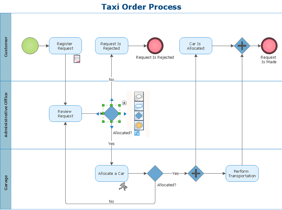
How to Make a Rapid Draw Object in ConceptDraw PRO
The Rapid Draw technology is an automatic drawing system. It is designed to significantly reduce the time of creating flowcharts and diagrams. Especially those, consisting from some typical entities. You can extend the standard ConceptDraw PRO object libraries with new objects by customizing any item from any library and assigning it with Rapid Draw features. You can quickly create and edit complex drawings using Rapid Draw technology and your self-created objects.
 Flowcharts
The Flowcharts Solution for ConceptDraw PRO v10 is a comprehensive set of examples and samples in several different color themes for professionals that need to graphically represent a process. Solution value is added by basic flow chart template and shapes' library of Flowchart notation. ConceptDraw PRO flow chart creator lets one depict a processes of any complexity and length, as well design of the flowchart either vertically or horizontally.
- Timeline Diagrams | How to Make a Timeline | Project Timeline ...
- How to Create a Timeline Diagram in ConceptDraw PRO | Project ...
- Timeline diagram | Timeline Diagrams | Project Timeline | Milestone ...
- Software Work Flow Process in Project Management with Diagram ...
- Timeline Diagrams
- Sample Project Flowchart. Flowchart Examples | Project ...
- Activity Network Diagram Method | How to Create Presentation of ...
- How To use House Plan Software | Process Flowchart | Construction ...
- Construction Project Team Structure Diagram
- How to Create a Timeline Diagram in ConceptDraw PRO | Timeline ...
- Timeline Diagrams | Examples of Flowcharts, Org Charts and More ...
- Process Flowchart | Business Diagram Software | Business ...
- How to Create a Timeline Diagram in ConceptDraw PRO | How to ...
- Gant Chart in Project Management | How to Create a Gantt Chart for ...
- Flowchart Of Making A Project
- 5 Processes Of Project Management Chart
- Timeline Diagrams | How to Make a Timeline | Timeline Diagrams ...
- UML Class Diagram Constructor | Circle-Spoke Diagrams | UML ...
- How to Create a Timeline Diagram in ConceptDraw PRO | How to ...
- Project — Assigning Resources | Project —Task Trees and ...


