Structured Systems Analysis and Design Method (SSADM) with ConceptDraw DIAGRAM
Structured Systems Analysis and Design Method (abbr. SSADM) is a method developed in Great Britain and accepted in 1993 as a national standard for information systems development and analysis. SSADM is based on Data Flow Diagrams and is characterized with presence of clear sequence of steps at projecting, analysis, and documenting of information system. It involves 6 main stages: analysis of existing system or estimation of practicability, requirements definition, determination of technical requirements and equipment cost, development of logical data model, projecting of logical requirements and specification them, physical projecting. Each of them is also divided into several steps defining the tasks that should be fulfilled at a given stage. The most important SSADM elements are flows modeling with help of DFD, data logic modeling with help of LDS (Logical Data Structure) and description of entities behavior. Applying of SSADM is easy with ConceptDraw DIAGRAM diagramming and vector drawing software and Data Flow Diagram solution.HelpDesk
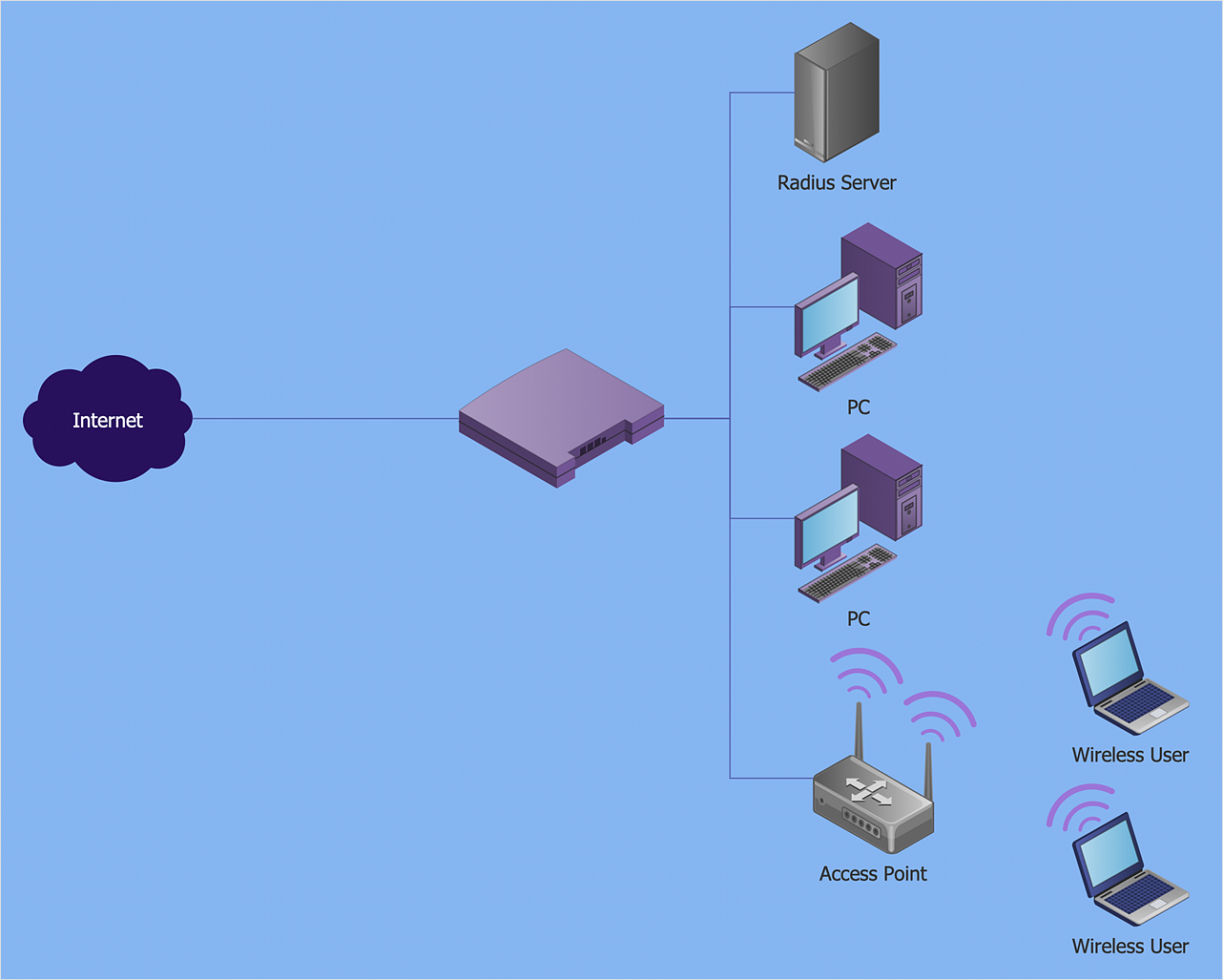
How to Create a Wireless Network Diagram Using ConceptDraw Solutions
A wireless network diagram is a specialized type of computer network diagrams. Wireless Network diagrams are used to develop, operate and maintain the WLAN systems. Making a Wireless Network diagram involves many different elements that can be managed using ConceptDraw DIAGRAM. With ConceptDraw DIAGRAM you can easily create and communicate the Wireless Network diagram of any complexity.HelpDesk
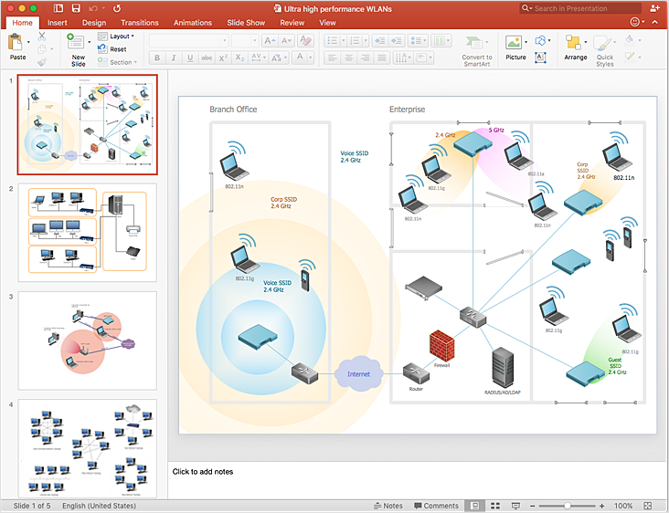
How to Add a Wireless Network Diagram to a PowerPoint Presentation
The PowerPoint presentation of the wireless network can be very informative. ConceptDraw DIAGRAM allows you to easily create wireless network diagrams and then make a PowerPoint Presentation from your diagrams in a single click.UML Use Case Diagram Example. Social Networking Sites Project
UML Diagrams Social Networking Sites Project. This sample was created in ConceptDraw DIAGRAM diagramming and vector drawing software using the UML Use Case Diagram library of the Rapid UML Solution from the Software Development area of ConceptDraw Solution Park. This sample shows the Facebook Socio-health system and is used at the projection and creating of the social networking sites.
 Data Flow Diagrams (DFD)
Data Flow Diagrams solution extends ConceptDraw DIAGRAM software with templates, samples and libraries of vector stencils for drawing the data flow diagrams (DFD).
How to Build Cloud Computing Diagram Principal Cloud Manufacturing
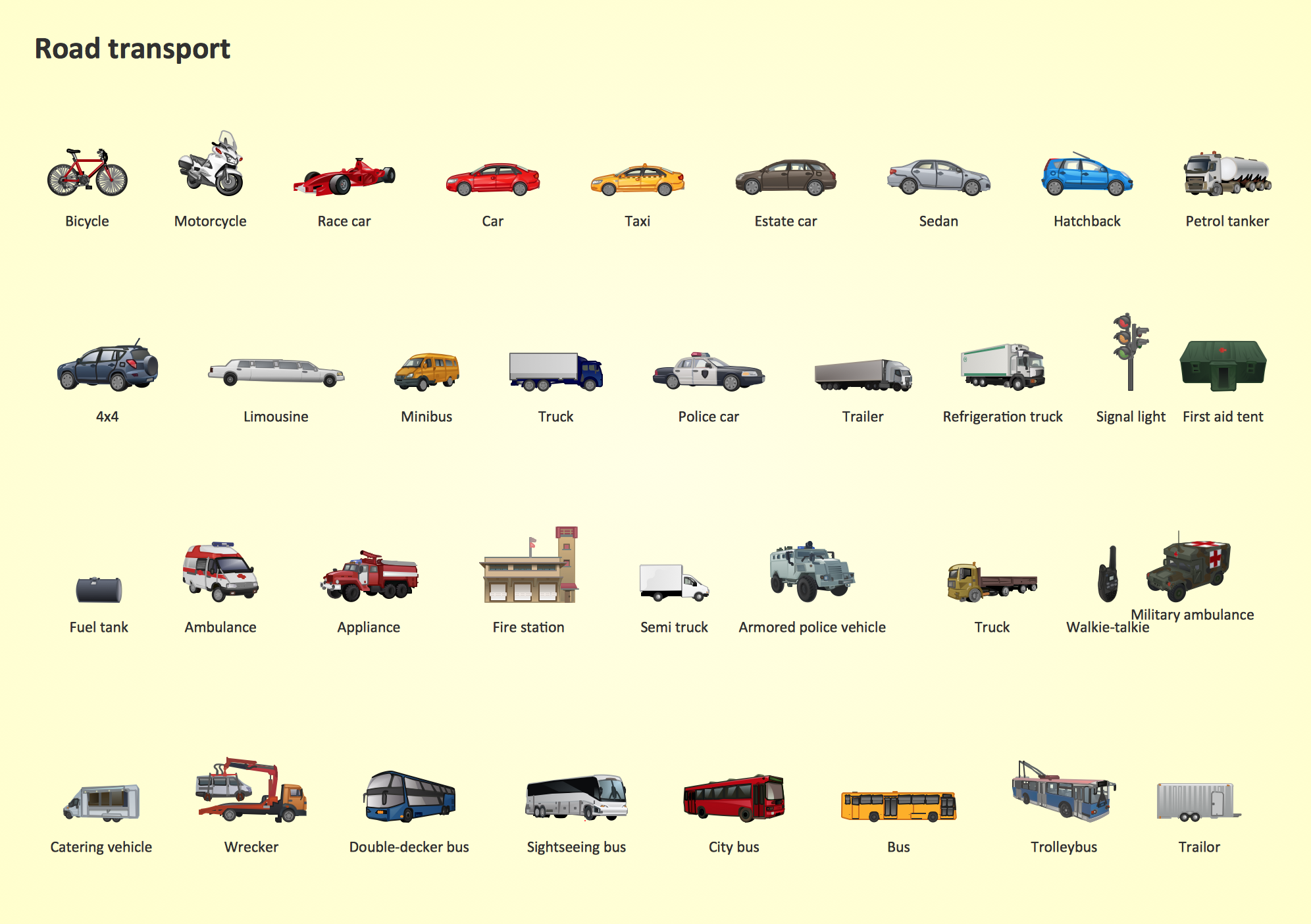
The term “cloud” is very popular and widely used now, it is a server, data processing centre, or a network which lets to store the data and software, provides access to them, allows to run applications without installation and gives the possibility to process data hosted remotely via the Internet connection. For documenting the Cloud Computing Architecture with a goal to facilitate the communication between stakeholders are successfully used the Cloud Computing Architecture diagrams. It is convenient and easy to draw various Cloud Computing Architecture diagrams in ConceptDraw DIAGRAM software with help of tools of the Cloud Computing Diagrams Solution from the Computer and Networks Area of ConceptDraw Solution Park.Road Transport - Design Elements
Samples, templates and libraries contain vector clip art for drawing the Road Transport Illustrations.- Fault Tree Analysis Software | Context Diagram Template | Process ...
- Context Diagram Template | Process Flowchart | Audiovisual system ...
- Context Diagram For Conversion System
- Example of DFD for Online Store ( Data Flow Diagram ) DFD ...
- Example of DFD for Online Store ( Data Flow Diagram ) DFD ...
- Data Flow Diagrams ( DFD ) | IDEF0 Diagrams | How to Create a ...
- Wireless Local Area Network Diagram
- IDEF0 Diagrams | Data Flow Diagrams | How to Add a Self-Drawn ...
- Network diagrams with ConceptDraw PRO | Internet Connectivity ...
- Example of DFD for Online Store ( Data Flow Diagram ) DFD ...
- Context Diagram Template | Top-level context diagram | DFD Library ...
- Hotel Network Topology Diagram | Mini Hotel Floor Plan. Floor Plan ...
- Context Diagram Template | Top-level context diagram | Data Flow ...
- Logical network topology diagram | Network diagrams with ...
- Network Topologies | Active Directory Diagrams | Football | Activity ...
- Wireless Networks | EIGRP. Computer and Network Examples ...
- Vehicular Networking | Wireless Networks | Telecommunication ...
- Interactive Voice Response Diagrams | How to Create an Interactive ...
- How to Draw a Computer Network Diagrams | BPR Diagram ...
- UML Use Case Diagram Example Social Networking Sites Project ...


