This site uses cookies. By continuing to browse the ConceptDraw site you are agreeing to our Use of Site Cookies.

Quality Control Chart Software — ISO Flowcharting

Quality Control Chart Software (ISO Flowcharting) - ConceptDraw DIAGRAM extended with Total Quality Management TQM Diagrams Solution from the Quality Management Area is the best diagramming and vector drawing software that allows you to draw the quality control charts quick and easy. The quality control chart is a graphic that illustrates the accordance of processes or products to the intended specifications and degree of differences from them. Depending on what type of data you need analyze, there are used different types of quality control charts: X-bar charts, S charts, Np charts.

Basic Diagramming

Create flowcharts, organizational charts, bar charts, line graphs, and more with ConceptDraw DIAGRAM.

Functional Block Diagram

You need design the Functional Block Diagram and dream to find the useful tools to draw it easier, quickly and effectively? ConceptDraw DIAGRAM offers the Block Diagrams Solution from the "Diagrams" Area which will help you!

Block Diagram

The vector stencils libraries: Block Diagrams, Blocks with Perspective, Callouts, Connectors, Raised Blocks from the solution Block Diagrams contain specific block diagram symbols such as arrows, input/output symbols, start/end symbols, processing symbols, conditional symbols, commenting symbols, callouts, connectors, etc. for ConceptDraw DIAGRAM diagramming and vector drawing software. The Block Diagrams solution is contained in a "Diagrams" area of ConceptDraw Solution Park. Use the libraries from the Block Diagrams solution to draw block diagrams for your business documents, presentations and websites in a few minutes.
This vector stencils library contains 22 IBD symbols.
Use it to design your internal block diagrams using ConceptDraw PRO diagramming and vector drawing software.
"Internal Block Diagram
An internal block diagram is based on the UML composite structure diagram, with restrictions and extensions as defined
by SysML. ...
Property types
Four general categories of properties of blocks are recognized in SysML: parts, references, value properties, and
constraint properties. ... A part or value property is always shown on an internal block diagram with a solid-outline box. A reference property is shown by a dashed-outline box, consistent with UML. Ports are special cases of properties, and have a variety of notations... Constraint properties and their parameters also have their own notations... " [www.omg.org/ spec/ SysML/ 1.3/ PDF]
The vector stencils library "Internal block diagram" is included in the SysML solution from the Software Development area of ConceptDraw Solution Park.
Internal block diagram
Internal block diagram, shared association, object node, internal block diagram, control operator frame,
Property
Property, property, interface block, interface,
Property 2
Property 2, property specific type, property, namespace compartment,
Actor part
Actor part, actor part,
Actor part 2
Actor part 2, actor part,
Property specific type
Property specific type, property specific type,
Property specific type 2
Property specific type 2, property specific type,
Dependency
Dependency, dependency,
Binding connector
Binding connector, binding connector,
Binding connector, equal
Binding connector, equal, binding connector,
Bidirectional connector
Bidirectional connector, bidirectional connector,
Unidirectional connector
Unidirectional connector, unidirectional connector,
Conjugated ports
Conjugated ports, port, object node, conjugated port,
Conjugated ports 2
Conjugated ports 2, port, object node, conjugated port,
Ports with flow properties
Ports with flow properties, port, object node,
Port (nested)
Port (nested), port, object node, nested port,
Proxy port
Proxy port, proxy port, port, object node,
Full port
Full port, port, object node, full port,
Item flow
Item flow, port, object node, item flow,
Item flow with an item property
Item flow with an item property, port, object node, item flow, item property,
Required and provided interfaces
Required and provided interfaces, required interface, required and provided interfaces, port, object node, interface,
Required and provided interfaces 2
Required and provided interfaces 2, required interface, required and provided interfaces, port, object node, interface,

flowchart maker, data flow diagram, swimlane diagram, business process modeling, how to create a flowchart Classic Business Process Modeling

flowchart maker, data flow diagram, swimlane diagram, business process modeling, how to create a flowchart
The ConceptDraw DIAGRAM software enhanced with Classic Business Process Modeling solution is a powerful flowchart maker and professional business process modeling software with extensive choice of drawing tools, libraries with wide variety of ready-to-use vector objects that are more than sufficient for modeling the business processes and for instant creation variety of diagram types: Control Flow Diagram, Swimlane Diagram, Business Process Modeling Diagram, Functional Flow Block Diagram, Data Flow Diagram. It is ideal for business analysts, developers, managers and regular users. The samples included to Classic Business Process Modeling solution allow you to uncover the solution’s power and answer qualitatively on how to create a flowchart or to model the business processes with help of diagrams and schemes.

System Block Diagram Software

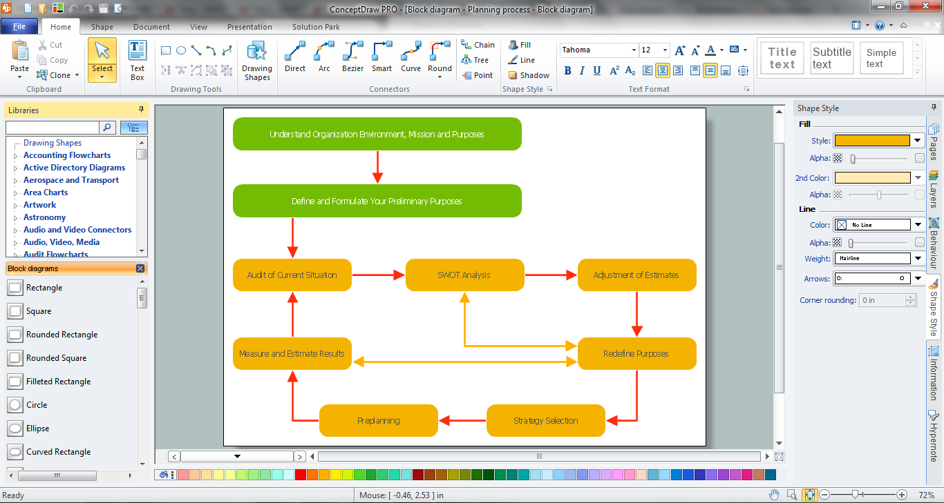
Block Diagrams solution makes ConceptDraw DIAGRAM a powerful system block diagram software. It enables you to work with all variety of tools you love in this software. The solution includes an enormous quantity of predesigned objects and connectors needed to design your Block Diagrams in minutes. The included templates and samples useful for a quick start. Use these tools to design extremely fast and simply Block Diagrams looking like those created by experts, even if you are a beginner.

How to Draw EPC Diagram Quickly

An event-driven process chain diagram is a flowchart used in business process analysis. It evolved from Architecture of Integrated Information Systems (ARIS) and utilised in the business process improvement and analysis. It is also used to facilitate enterprise resource planning. An EPC diagram is a complex flowchart that shows different business processes through various workflows. The workflows are seen as functions and events that are connected by different teams or people, as well as tasks that allow business processes to be executed. ConceptDraw DIAGRAM is a software for making EPC diagrams that allows managers visually present business process models for making decisions for business.
How to Draw EPC Diagram

amplifiers, electrical engineering, electrical symbols, pulses Electronic Block Diagrams

amplifiers, electrical engineering, electrical symbols, pulses
The Electronic Block Diagrams solution for ConceptDraw DIAGRAM includes a set of diagrams samples and a large number of specialized electronic and electrical symbols of electronic blocks, amplifiers, pulses, repeaters, converters, waveforms, electric filters, delay elements, etc. All symbols are highly simple and common for electronics. They allow designing strict and clear diagrams and electronics graphical designs for documentation, specifications, reports, presentation slides. Use them in electrical engineering, to design and construct electronic equipment, show sequence of pulses and flow of energy, and rapidly identify points of interest or trouble spots in electronic circuits.

Flowcharting Software

A flowchart is a useful type of diagram quite popular in many areas of science and business, which represents some algorithm, workflow or process. ConceptDraw DIAGRAM diagramming and vector graphic software extended with Flowcharts solution from the "Diagrams" area of ConceptDraw Solution Park is also ideal flowcharting software with powerful tools that assist in easily making the Flowcharts of different types and directions, in representing the flowchart steps and describing the flowchart processes, in realizing the flowchart constructions, creating the process flow models, designing the data flow diagrams, and many other flowcharting related diagrams. ConceptDraw DIAGRAM software maximally facilitates the drawing process by means of included predesigned vector objects, which only need to be dragged to your ConceptDraw document from the corresponding library and connected with smart connectors. This way lets equally easy make the simple flowcharts, as well as flowcharts of complex processes and procedures.

Basic Diagramming

Try ConceptDraw program, the perfect drawing tool for creating all kinds of great-looking drawings, charts, graphs, and illustrations.

What is Electrical Engineering?
Basic Electrical Engineering Software

Electrical engineering is a field of engineering that generally deals with the study and application of electricity, electronics, and electromagnetism. ConceptDraw DIAGRAM extended with Electrical Engineering Solution from the Industrial Engineering Area of ConceptDraw Solution Park is the best Electrical Engineering software. You have an excellent possibility to make sure this right now.

Electrical Block Diagram Software

Block Diagrams are a kind of universal diagrams used by many specialists. The computer experts can use Block Diagrams to depict computer systems, the engineers have the possibility to plan the manufacturing processes, electrical engineering processes, etc. ConceptDraw DIAGRAM has an intuitive and beginner-friendly interface. Being extended with the Block Diagrams solution it is a powerful electrical Block Diagram software.

Simple Flow Chart

ConceptDraw DIAGRAM diagramming and vector drawing software extended with Flowcharts Solution from the 'Diagrams' area of ConceptDraw Solution Park is a powerful tool for drawing Flow Charts of any complexity you need. Irrespective of whether you want to draw a Simple Flow Chart or large complex Flow Diagram, you estimate to do it without efforts thanks to the extensive drawing tools of Flowcharts solution, there are professional flowchart symbols and basic flowchart symbols. This sample shows the Gravitational Search Algorithm (GSA) that is the optimization algorithm.

physical security plan, security chart, access chart, security plans, access schemes, access plans , CCTV Security and Access Plans

physical security plan, security chart, access chart, security plans, access schemes, access plans , CCTV
The Security and Access Plans solution may be utilized in order to develop detailed equipment and cabling layout plans, blueprints, and wiring diagrams on internal and external security and access control systems, video surveillance and closed-circuit television (CCTV) systems. IT specialists, security managers, and other guards may use it to quickly design security plans and access plans, security chart, physical security plan, access chart, or access scheme on desire.

Best Multi-Platform Diagram Software

ConceptDraw DIAGRAM is a powerful tool for drawing business communication ideas and concepts, simple visual presentation of numerical data in the Mac environment.

Piping and Instrumentation Diagram Software

Piping and Instrumentation Diagram is a technical sketch or drawing, which shows in details the piping system and instrumentation of a processing plant. Piping and Instrumentation Diagram is developed by process design engineers and technical engineers on the phase of plant design. This plan is necessary on the stages of plant construction and then is actively used by operators, instrumentation and piping engineers when operating the plant. ConceptDraw DIAGRAM software provides unique Plumbing and Piping Plans solution from Building Plans area of ConceptDraw Solution Park with 10 libraries of ready-to-use predesigned vector elements, templates and samples, to help you create professional Piping diagrams and schematics, Instrumentation diagrams, Plumbing plans and blueprints, Schemes of hot and cold water supply systems, Heating schemes, Mechanical diagrams, Diagrams of fluids, hydraulics, air and gas pipings, Technical drawings of waste water disposal systems, Schematics of industrial piping systems, Diagrams of ventilation systems, etc.

SysML Diagram

To draw SysML diagrams use the ConceptDraw DIAGRAM diagramming and vector drawing software extended with the Rapid UML solution from the Software Development area of ConceptDraw Solution Park.
This vector stencils library contains 54 BDD symbols.
Use it to design your block definition diagrams using ConceptDraw PRO diagramming and vector drawing software.
"Block Definition Diagram
A block definition diagram is based on the UML class diagram, with restrictions and extensions as defined by SysML. ...
Block and ValueType Definitions
A SysML Block defines a collection of features to describe a system or other element of interest. A SysML ValueType
defines values that may be used within a model. SysML blocks are based on UML classes, as extended by UML composite structures. SysML value types are based on UML data types. Diagram extensions for SysML blocks and value types are described by other subheadings of this sub clause." [www.omg.org/ spec/ SysML/ 1.3/ PDF]
The vector stencils library "Block definition diagram" is included in the SysML solution from the Software Development area of ConceptDraw Solution Park.
Block definition diagram
Block definition diagram, object node, control operator frame, block definition diagram,
Block
Block, block,
Actor
Actor, actor,
Actor 2
Actor 2, actor,
Value type
Value type, value type,
Enumeration
Enumeration, enumeration,
Abstract definition
Abstract definition, abstract definition,
Abstract definition 2
Abstract definition 2, abstract definition,
Abstract definition 3
Abstract definition 3, abstract definition,
Stereotype property compartment
Stereotype property compartment, stereotype property compartment,
Namespace compartment
Namespace compartment, object node, namespace compartment,
Structure compartment
Structure compartment, structure compartment, object node,
Unit
Unit, unit,
Unit 2
Unit 2, unit,
Quantity kind
Quantity kind, quantity kind,
Instance specification
Instance specification, object node, instance specification,
Instance specification 2
Instance specification 2, instance specification,
Instance specification 3
Instance specification 3, instance specification,
Instance specification 4
Instance specification 4, structure compartment, instance specification,
Dependency
Dependency, dependency,
Reference association
Reference association, reference association,
Reference association 2
Reference association 2, reference association,
Part association
Part association, part association,
Part association 2
Part association 2, part association,
Shared association
Shared association, shared association,
Shared association 2
Shared association 2, shared association,
Multibranch part association
Multibranch part association, multibranch part association,
Multibranch shared association
Multibranch shared association, multibranch shared association,
Generalization
Generalization, generalization,
Multibranch generalization
Multibranch generalization, multibranch generalization,
Generalization set, disjoint
Generalization set, disjoint, disjoint generalization set,
Generalization set, overlapping
Generalization set, overlapping, overlapping generalization set,
Block namespace containment
Block namespace containment, block namespace containment,
Participant property
Participant property, reference association, participant property, object node, connector property,
Participant property 2
Participant property 2, structure compartment, reference association, participant property, object node, actor,
Participant property 3
Participant property 3, reference association, participant property, object node,
Connector property
Connector property, object node, connector property,
Conjugated ports
Conjugated ports, port, object node, conjugated port,
Conjugated ports 2
Conjugated ports 2, port, object node, conjugated port,
Ports with flow properties
Ports with flow properties, port, object node,
Port (compartment notation)
Port (compartment notation), port,
Port (nested)
Port (nested), port, object node, nested port,
Proxy port
Proxy port, proxy port, port, object node,
Full port
Full port, port, object node, full port,
Flow property
Flow property, flow property,
Required and provided features
Required and provided features, required and provided features,
Interface block
Interface block, interface block, interface,
Item flow
Item flow, port, object node, item flow,
Item flow 2
Item flow 2, port, object node, item flow, item property,
Item flow 3
Item flow 3, port, object node, item flow, connector property,
Interface
Interface, interface,
Required and provided interfaces
Required and provided interfaces, required interface, required and provided interfaces, port, object node, interface,
Required and provided interfaces 2
Required and provided interfaces 2, required interface, required and provided interfaces, port, object node, interface,
Constraint block
Constraint block, constraint block,