Structured Systems Analysis and Design Method (SSADM) with ConceptDraw DIAGRAM
Structured Systems Analysis and Design Method (abbr. SSADM) is a method developed in Great Britain and accepted in 1993 as a national standard for information systems development and analysis. SSADM is based on Data Flow Diagrams and is characterized with presence of clear sequence of steps at projecting, analysis, and documenting of information system. It involves 6 main stages: analysis of existing system or estimation of practicability, requirements definition, determination of technical requirements and equipment cost, development of logical data model, projecting of logical requirements and specification them, physical projecting. Each of them is also divided into several steps defining the tasks that should be fulfilled at a given stage. The most important SSADM elements are flows modeling with help of DFD, data logic modeling with help of LDS (Logical Data Structure) and description of entities behavior. Applying of SSADM is easy with ConceptDraw DIAGRAM diagramming and vector drawing software and Data Flow Diagram solution.
 Data Flow Diagrams (DFD)
Data Flow Diagrams solution extends ConceptDraw DIAGRAM software with templates, samples and libraries of vector stencils for drawing the data flow diagrams (DFD).
Context Diagram Template
This template shows the Context Diagram. It was created in ConceptDraw DIAGRAM diagramming and vector drawing software using the Block Diagrams Solution from the “Diagrams” area of ConceptDraw Solution Park. The context diagram graphically identifies the system. external factors, and relations between them. It’s a high level view of the system. The context diagrams are widely used in software engineering and systems engineering for designing the systems that process the information.
 IDEF0 Diagrams
IDEF0 Diagrams visualize system models using the Integration Definition for Function Modeling (IDEF) methodology. Use them for analysis, development and integration of information and software systems, and business process modelling.
Pyramid Diagram
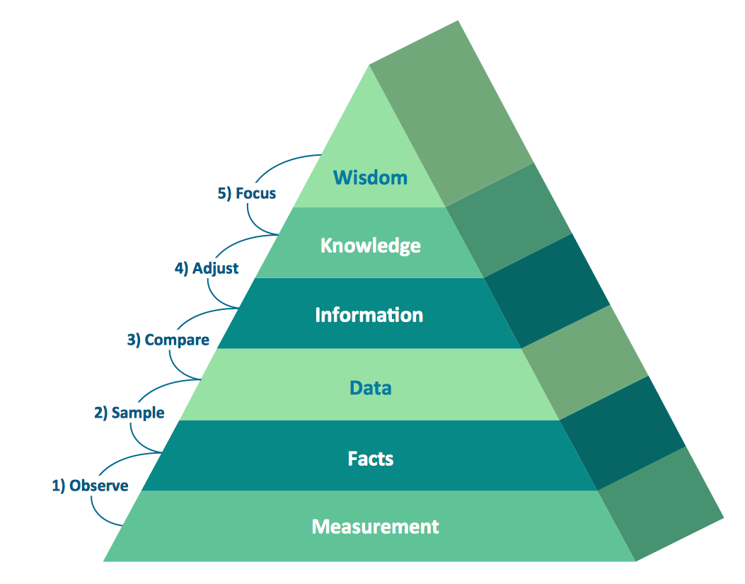
Pyramid diagrams help you visualize information as a triangle divided into horizontal slices. Labelled slices represent a hierarchy. Pyramids are used in marketing presentations to show and analyze hierarchy levels. 3D triangular diagram of DIKW pyramid has 6 levels: measurement, facts, data, information, knowledge, wisdom. The data component include different scattered signs or symbols which are merely useless until these random objective facts are somehow processed. Data is a resource which has to be manipulated or rearranged to get useful. Information can be extracted from a pile of data, it also can be mined from different data storages.Is ConceptDraw DIAGRAM an Alternative to Microsoft Visio?
Visio for Mac and Windows - ConceptDraw as an alternative to MS Visio. ConceptDraw DIAGRAM delivers full-functioned alternative to MS Visio. ConceptDraw DIAGRAM supports import of Visio files. ConceptDraw DIAGRAM supports flowcharting, swimlane, orgchart, project chart, mind map, decision tree, cause and effect, charts and graphs, and many other diagram types.- Data Flow Diagrams (DFD) | IDEF0 Diagrams | IDEF0 Visio | Dfd For ...
- Data Flow Diagram For Library Management System Pdf
- IDEF0 Diagrams | Data Flow Diagrams (DFD) | Management ...
- DFD Library System | Data Flow Diagrams (DFD) | Data Flow ...
- DFD Library System | Data Flow Diagram Symbols. DFD Library ...
- Data Flow Diagrams (DFD) | Data Flow Diagrams | Data Flow ...
- Data Flow Diagrams
- Data Flow Diagrams | Data Flow Diagram | Data Flow Diagram ...
- DFD Library System | Data Flow Diagrams (DFD) | Audio, Video ...
- Data Flow Diagrams (DFD) | IDEF0 Diagrams | How to Create a ...
- DFD Library System | Data Flow Diagram Symbols. DFD Library ...
- Data Flow Diagrams (DFD) | DFD Library System | Data Flow ...
- DFD Library System | Data Flow Diagrams (DFD) | Example of DFD ...
- Data Flow Diagrams (DFD) | Pyramid Diagrams | Network Layout ...
- Levels Of Dataflow Daigrams For Library Management
- Data Flow Diagram (DFD) | Context Diagram Template | DFD Library ...
- DFD Library System | Data Flow Diagram Symbols. DFD Library ...
- DFD Library System | Data Flow Diagrams (DFD) | Data Flow ...
- Data Flow Diagrams (DFD) | IDEF0 Diagrams | Process Flowchart ...
- DFD Library - Design elements | Data Flow Diagrams (DFD ...


