Bubble diagrams in Landscape Design with ConceptDraw DIAGRAM
Bubble Diagrams are the charts with a bubble presentation of data with obligatory consideration of bubble's sizes. They are analogs of Mind Maps and find their application at many fields, and even in landscape design. At this case the bubbles are applied to illustrate the arrangement of different areas of future landscape design, such as lawns, flowerbeds, playgrounds, pools, recreation areas, etc. Bubble Diagram helps to see instantly the whole project, it is easy for design and quite informative, in most cases it reflects all needed information. Often Bubble Diagram is used as a draft for the future landscape project, on the first stage of its design, and in case of approval of chosen design concept is created advanced detailed landscape plan with specification of plants and used materials. Creation of Bubble Diagrams for landscape in ConceptDraw DIAGRAM software is an easy task thanks to the Bubble Diagrams solution from "Diagrams" area. You can use the ready scanned location plan as the base or create it easy using the special ConceptDraw libraries and templates.The vector stencils library "Network layout floorplan" contain 34 symbol icons for drawing computer network floor plans, communication equipment layouts, and structured cabling diagrams.
"Structured cabling is building or campus telecommunications cabling infrastructure that consists of a number of standardized smaller elements (hence structured) called subsystems. ...
Structured cabling design and installation is governed by a set of standards that specify wiring data centers, offices, and apartment buildings for data or voice communications using various kinds of cable, most commonly category 5e (CAT-5e), category 6 (CAT-6), and fibre optic cabling and modular connectors. These standards define how to lay the cabling in various topologies in order to meet the needs of the customer, typically using a central patch panel (which is normally 19 inch rack-mounted), from where each modular connection can be used as needed. Each outlet is then patched into a network switch (normally also rack-mounted) for network use or into an IP or PBX (private branch exchange) telephone system patch panel." [Structured cabling. Wikipedia]
The design elements example "Network layout floorplan - Vector stencils library" was created using the ConceptDraw PRO diagramming and vector drawing software extended with the Network Layout Floor Plans solution from the Computer and Networks area of ConceptDraw Solution Park.
HelpDesk
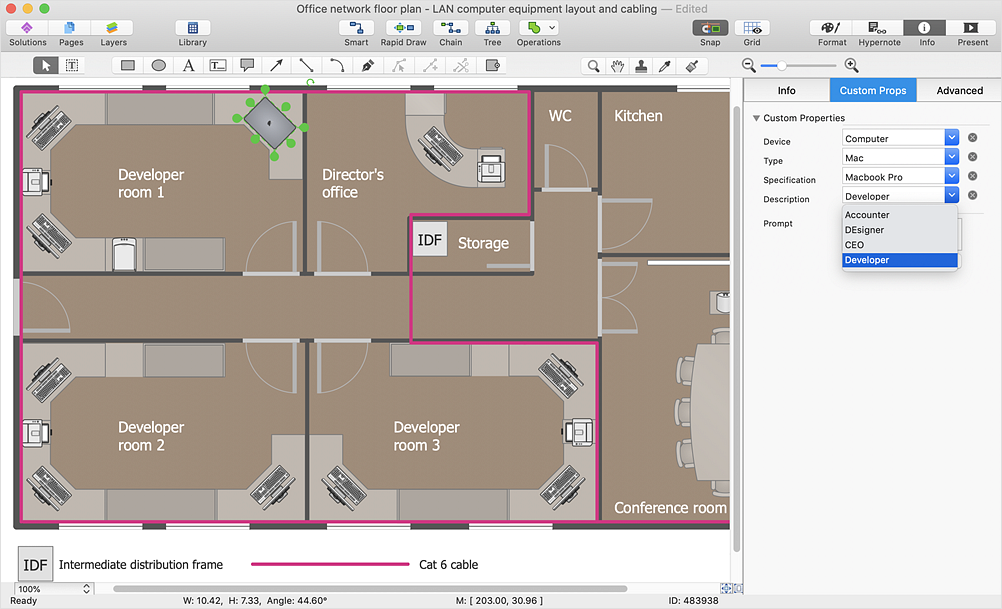
How to Work with Custom Properties
ConceptDraw DIAGRAM can store additional, user-defined data that can be assigned to a particular shape. This data is stored in the Custom Properties options.HelpDesk
How to Create a New Library
Sometimes, when creating a diagram, you need to use a large set of elements from different libraries. If you are using ConceptDraw , in such case, we recommend you to create a new library, which consists of vector library objects from other ConceptDraw libraries. You also can add some custom unique objects into such library. Each object that contains in a new library can be provided with a unique description and keyword list. Thus, the new library and its objects will be indexed to be searched and used in the further diagrams.HelpDesk
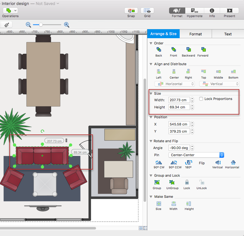
How to Change the Measurement Units and Drawing Scale
ConceptDraw DIAGRAM allows you to work with drawings with many different measurement units.HelpDesk
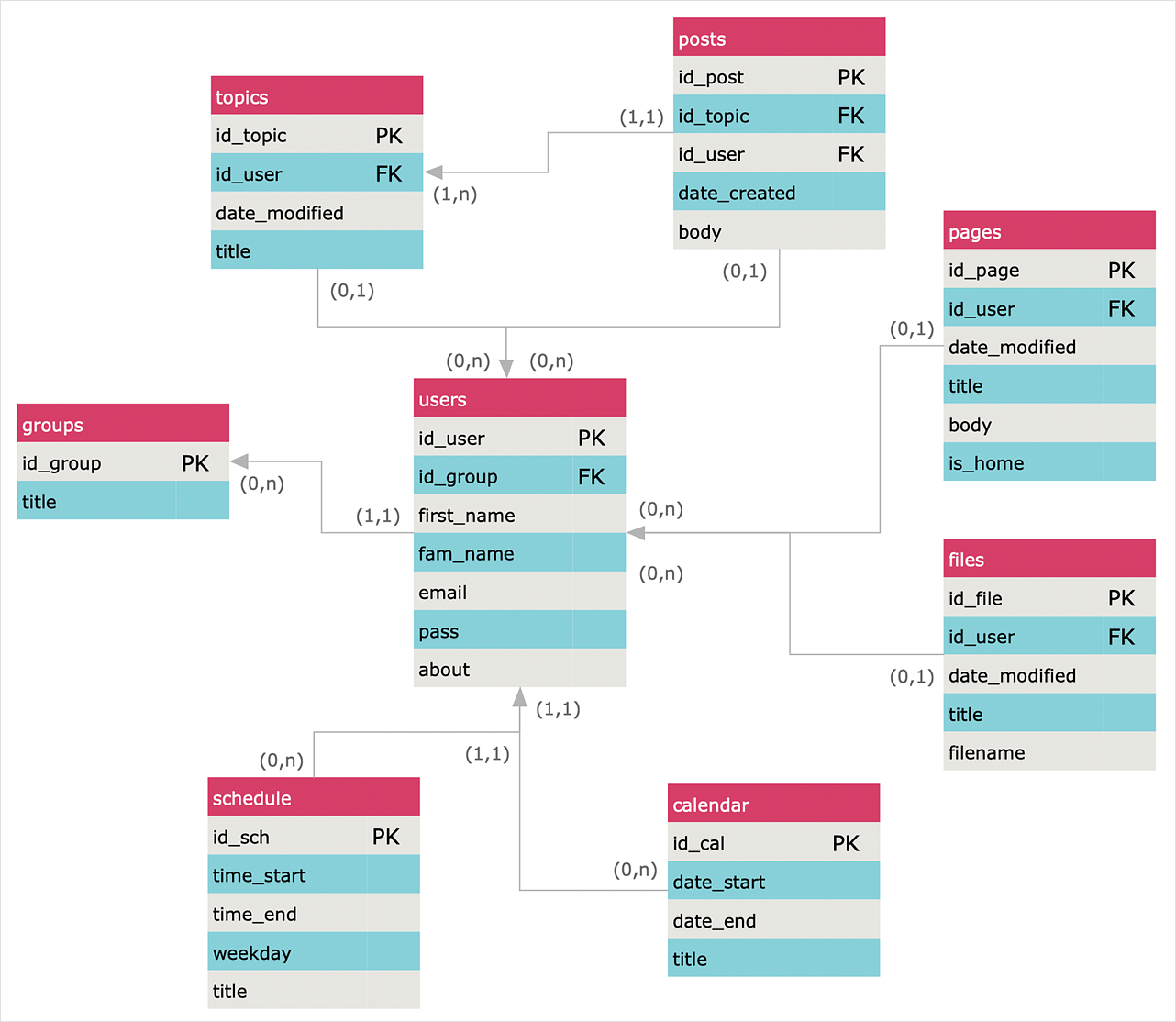
How to Create an Entity-Relationship Diagram
ERD (entity relationship diagram) is used to show the logical structure of databases. It represents the interrelationships between components of a database (entities). Entity relationship diagrams are widely used in software engineering. Using ERD software engineers can control every aspect of database development. ER diagram can be used as the guide for testing and communicating before the release of a software product. ERD displays data as entities that are connected with connections that show the relationships between entities. There are some ERD notations used by databases developers for representing the relationships between the data objects. ConceptDraw DIAGRAM and its ERD solution allow you to build ERD diagram of any notation.- How to Create a Floor Plan Using ConceptDraw PRO | Design ...
- Define Can Campus Area Network
- Basic Flowchart Symbols and Meaning | How To Create Restaurant ...
- Floor Plans | Network layout floorplan - Vector stencils library | Room ...
- Network Layout Floor Plans | Design elements - Network layout ...
- Cafe and Restaurant Floor Plans | Sports bar - Floor plan | How To ...
- Basic Flowchart Symbols and Meaning | Design elements - Network ...
- How To use House Electrical Plan Software | Restaurant Floor Plans ...
- Ethernet local area network layout floor plan | Network layout ...
- Network Layout Floor Plans | Network layout floorplan - Vector ...
- Design elements - Network layout floorplan | Network Layout Floor ...
- DVI pinout diagram | Design elements - Audio and video connectors ...
- Reflected Ceiling Plans | How to Create a Reflected Ceiling Floor ...
- Process Flowchart | Design elements - Process annotations | How ...
- How To Create Restaurant Floor Plan in Minutes | Emergency Plan ...
- Lighting and switch layout
- Process Flowchart | Basic Flowchart Symbols and Meaning | How To ...
- Electrical Symbols Definition
- Fire Evacuation Plan Template | How To Create Restaurant Floor ...
- How To Create Restaurant Floor Plan in Minutes | Flow Chart Online ...


