Bubble diagrams in Landscape Design with ConceptDraw DIAGRAM
Bubble Diagrams are the charts with a bubble presentation of data with obligatory consideration of bubble's sizes. They are analogs of Mind Maps and find their application at many fields, and even in landscape design. At this case the bubbles are applied to illustrate the arrangement of different areas of future landscape design, such as lawns, flowerbeds, playgrounds, pools, recreation areas, etc. Bubble Diagram helps to see instantly the whole project, it is easy for design and quite informative, in most cases it reflects all needed information. Often Bubble Diagram is used as a draft for the future landscape project, on the first stage of its design, and in case of approval of chosen design concept is created advanced detailed landscape plan with specification of plants and used materials. Creation of Bubble Diagrams for landscape in ConceptDraw DIAGRAM software is an easy task thanks to the Bubble Diagrams solution from "Diagrams" area. You can use the ready scanned location plan as the base or create it easy using the special ConceptDraw libraries and templates."In computer networks, networked computing devices pass data to each other along data connections. The connections (network links) between nodes are established using either cable media or wireless media. ...
Network computer devices that originate, route and terminate the data are called network nodes. Nodes can include hosts such as personal computers, phones, servers as well as networking hardware. ...
Network links.
The communication media used to link devices to form a computer network include electrical cable (HomePNA, power line communication, G.hn), optical fiber (fiber-optic communication), and radio waves (wireless networking). In the OSI model, these are defined at layers 1 and 2 - the physical layer and the data link layer.
A widely adopted family of communication media used in local area network (LAN) technology is collectively known as Ethernet. The media and protocol standards that enable communication between networked devices over Ethernet are defined by IEEE 802.3. Ethernet transmit data over both copper and fiber cables. Wireless LAN standards (e.g. those defined by IEEE 802.11) use radio waves, or others use infrared signals as a transmission medium. Power line communication uses a building's power cabling to transmit data. ...
Network nodes.
Apart from the physical communications media described above, networks comprise additional basic system building blocks, such as network interface controller (NICs), repeaters, hubs, bridges, switches, routers, modems, and firewalls." [Computer network. Wikipedia]
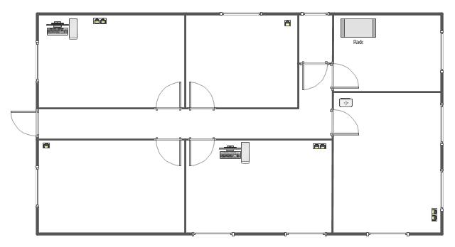
The network equipment and cabling layout floorplan template for the ConceptDraw PRO diagramming and vector drawing software is included in the Network Layout Floor Plans solution from the Computer and Networks area of ConceptDraw Solution Park.
- Electrical Layout Definition
- Power Layout Definition
- Lighting and switch layout | Reflected ceiling plan | Classroom ...
- How To use House Electrical Plan Software | Electrical Drawing ...
- Power socket outlet layout | Plant Layout Plans | Electrical and ...
- Draw And Explain The Layout Electrical Power System
- How To use House Electrical Plan Software | Store Layout Software ...
- Plant Layout Plans | Design elements - Stations | Electrical Drawing ...
- How To use House Electrical Plan Software | ConceptDraw Solution ...
- Office Layout Plans | Electrical Symbols, Electrical Diagram Symbols ...
- How To use House Electrical Plan Software | Electrical Drawing ...
- Wiring Diagrams with ConceptDraw PRO | Wiring Diagram Floor ...
- Electrical Drawing Software and Electrical Symbols | Technical ...
- How to Create a Floor Plan for the Classroom | Classroom plan ...
- Floor Plans | Interior Design Office Layout Plan Design Element ...
- Electrical Design Layout For A Factory
- Wiring Diagrams with ConceptDraw PRO | Design elements ...
- How Would A Flow Chart Help In Service Layout Planning
- How To use House Electrical Plan Software | Technical Drawing ...
- Plant Layout Plans | Emergency Plan | Process Flowchart | Factory ...

