 Computer and Networks Area
The solutions from Computer and Networks Area of ConceptDraw Solution Park collect samples, templates and vector stencils libraries for drawing computer and network diagrams, schemes and technical drawings.
 Network Layout Floor Plans
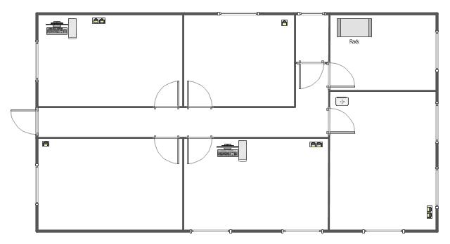
Network Layout Floor Plans solution extends ConceptDraw PRO software functionality with powerful tools for quick and efficient documentation the network equipment and displaying its location on the professionally designed Network Layout Floor Plans. Never before creation of Network Layout Floor Plans, Network Communication Plans, Network Topologies Plans and Network Topology Maps was not so easy, convenient and fast as with predesigned templates, samples, examples and comprehensive set of vector design elements included to the Network Layout Floor Plans solution. All listed types of plans will be a good support for the future correct cabling and installation of network equipment.
"In computer networks, networked computing devices pass data to each other along data connections. The connections (network links) between nodes are established using either cable media or wireless media. ...
Network computer devices that originate, route and terminate the data are called network nodes. Nodes can include hosts such as personal computers, phones, servers as well as networking hardware. ...
Network links.
The communication media used to link devices to form a computer network include electrical cable (HomePNA, power line communication, G.hn), optical fiber (fiber-optic communication), and radio waves (wireless networking). In the OSI model, these are defined at layers 1 and 2 - the physical layer and the data link layer.
A widely adopted family of communication media used in local area network (LAN) technology is collectively known as Ethernet. The media and protocol standards that enable communication between networked devices over Ethernet are defined by IEEE 802.3. Ethernet transmit data over both copper and fiber cables. Wireless LAN standards (e.g. those defined by IEEE 802.11) use radio waves, or others use infrared signals as a transmission medium. Power line communication uses a building's power cabling to transmit data. ...
Network nodes.
Apart from the physical communications media described above, networks comprise additional basic system building blocks, such as network interface controller (NICs), repeaters, hubs, bridges, switches, routers, modems, and firewalls." [Computer network. Wikipedia]
The network equipment and cabling layout floorplan template for the ConceptDraw PRO diagramming and vector drawing software is included in the Network Layout Floor Plans solution from the Computer and Networks area of ConceptDraw Solution Park.
 SYSML
SYSML
The SysML solution helps to present diagrams using Systems Modeling Language; a perfect tool for system engineering.
 Audit Flowcharts
Audit flowcharts solution extends ConceptDraw PRO software with templates, samples and library of vector stencils for drawing the audit and fiscal flow charts.
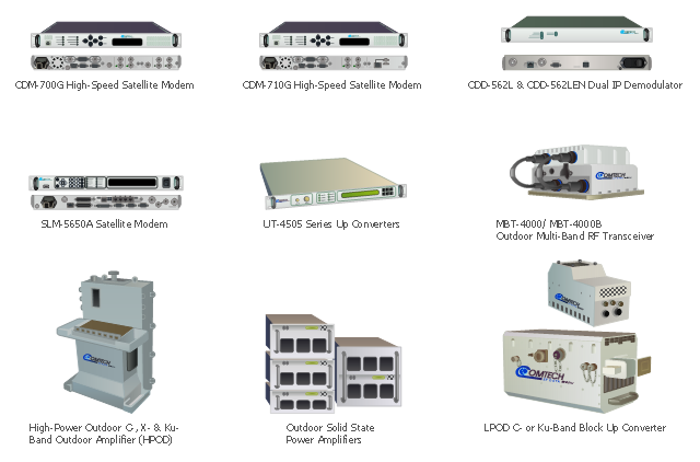
Comtech EF Data Corporation is the vendor of telecommunication solutions for fixed and mobile/ transportable satellite-based applications: Advanced VSAT Solutions, Modems, RAN & WAN Optimization, Managed Bandwidth, RF Products. [comtechefdata.com]
The telecom equipment clipart icons example "Design elements - Comtech" was created using the ConceptDraw PRO diagramming and vector drawing software extended with the Telecommunication Network Diagrams solution from the Computer and Networks area of ConceptDraw Solution Park.
The telecom equipment clipart icons example "Design elements - Comtech" was created using the ConceptDraw PRO diagramming and vector drawing software extended with the Telecommunication Network Diagrams solution from the Computer and Networks area of ConceptDraw Solution Park.
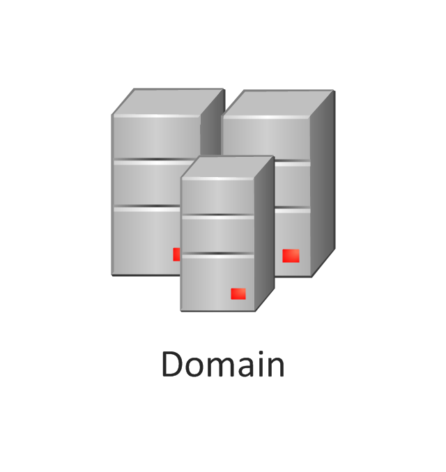
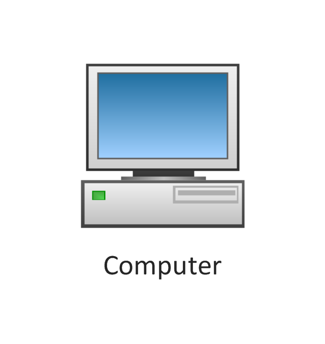
The vector stencils library "Active Directory" contains 20 symbols of Active Directory elements for drawing AD network diagrams. It helps network and system administrators to visualize Microsoft Windows Active Directory structures for network design, installation and maintainance.
"An Active Directory structure is an arrangement of information about objects. The objects fall into two broad categories: resources (e.g., printers) and security principals (user or computer accounts and groups). Security principals are assigned unique security identifiers (SIDs).
Each object represents a single entity - whether a user, a computer, a printer, or a group - and its attributes. Certain objects can contain other objects. An object is uniquely identified by its name and has a set of attributes - the characteristics and information that the object represents - defined by a schema, which also determines the kinds of objects that can be stored in Active Directory.
The schema object lets administrators extend or modify the schema when necessary. However, because each schema object is integral to the definition of Active Directory objects, deactivating or changing these objects can fundamentally change or disrupt a deployment. Schema changes automatically propagate throughout the system. Once created, an object can only be deactivated - not deleted. Changing the schema usually requires planning. Sites are implemented as a set of well-connected subnets." [Active Directory. Wikipedia]
The AD symbols example "Active Directory - Vector stencils library" was created using the ConceptDraw PRO diagramming and vector drawing software extended with the Active Directory Diagrams solution from the Computer and Networks area of ConceptDraw Solution Park.
www.conceptdraw.com/ solution-park/ active-directory-diagrams
- ConceptDraw Solution Park | Hotel Network Topology | Active ...
- Computer network - Vector stencils library | Software Defined ...
- Computer and Networks Area | Cisco Design | Network Glossary ...
- Tree Network Topology Diagram | Network Topologies | Computer ...
- Campus Area Networks (CAN). Computer and Network Examples ...
- Software Defined Networking System Overview | Network ...
- Metropolitan area networks (MAN). Computer and Network Examples
- Tree Network Topology Diagram | Fully Connected Network ...
- Campus Area Networks (CAN). Computer and Network Examples ...
- Network Gateway Router | Network Glossary Definition | Mesh ...
- Wide area network (WAN) topology. Computer and Network ...
- Network wiring cable. Computer and Network Examples | Network ...
- Computer and Networks Area | Software Defined Networking ...
- Campus Area Networks (CAN). Computer and Network Examples ...
- Network Gateway Router | Communication network diagram ...
- Network Gateway Router | Network Glossary Definition | Star ...
- Basic Flowchart Symbols and Meaning | ConceptDraw Solution Park ...
- Campus Area Networks (CAN). Computer and Network Examples ...
- Star Network Topology | Wireless Network WLAN | Tree Network ...
- Metropolitan area networks (MAN). Computer and Network Examples
