Data Flow Diagram
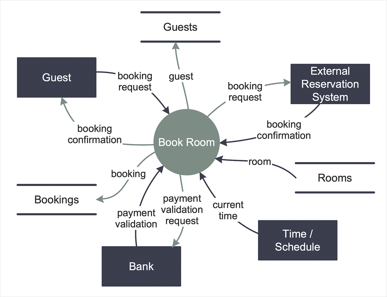
Data Flow Diagram (DFD) is the part of the Structured Systems Analysis and Design Methodology (SSADM), which is intended for information systems projection and analysis. Data Flow Diagrams allow graphically represent the data flows in information system and analyze the data processing during the structural projection. This type of diagrams lets visually show a work of information system and results of this work, it is often used in connection with human processes and can be displayed as Workflow diagram. Data Flow Diagram visualizes processes and functions, external entities, data depositories, and data flows connecting these elements and indicating direction and data character. Each of these elements used for DFD has its own graphical notation. There are two notations to draw DFDs - Yourdon & Coad and Gane & Sarson. ConceptDraw DIAGRAM extended with Data Flow Diagrams (DFD) solution from Software Developmant area is ideal for designing professional looking DFDs, which can be then easily exported in various formats.HelpDesk
How to Create a Data Flow Diagram
Data flow diagramming is a highly effective technique for showing the flow of information through a system. Data flow diagrams reveal relationships among and between the various components in a program or system. DFD is an important technique for modeling a system’s high-level detail by showing how input data is transformed to output results through a sequence of functional transformations. The set of standard symbols is used to depict how these components interact in a system. ConceptDraw DIAGRAM allows you to draw a simple and clear Data Flow Diagram using special libraries.Control and Information Architecture Diagrams (CIAD) with ConceptDraw DIAGRAM
One of the three main constituents of any enterprise is the Control and Information Architecture. The rest two are Production facilities and People and Organization.- Data Flow Diagram | Flow Diagram On Depository System Functions
- Data Flow Diagram | Working Of Depository In Diagram Form
- Data Flow Diagram | Depository System Flowchart
- Data Flow Diagram
- Data Flow Diagrams | Flowchart | Process Modelling using Event ...
- Example of DFD for Online Store (Data Flow Diagram ) DFD ...
- Basic Data Flow Diagram
- Dataflow Diagram For Import And Export Business
- Basic Flowchart Symbols and Meaning | Data Flow Diagram | Types ...
- How To Make Data Flow Diagram On Mac For Free
- Data Flow Diagram For Image Processing
- Data Flow Diagrams
- Data Flow Diagram
- How to Create a Data Flow Diagram using ConceptDraw PRO | Data ...
- Data Flow Diagram
- Data Flow Diagram | How To Create Restaurant Floor Plan in ...
- Workflow Diagrams
- Process Flowchart | Data Flow Diagram | How to Create Flowcharts ...
- Data Flow Diagrams | Basic Flowchart Symbols and Meaning | Data ...
- Data Flow Diagrams | Visualize Sales Data Using Sample Data ...


