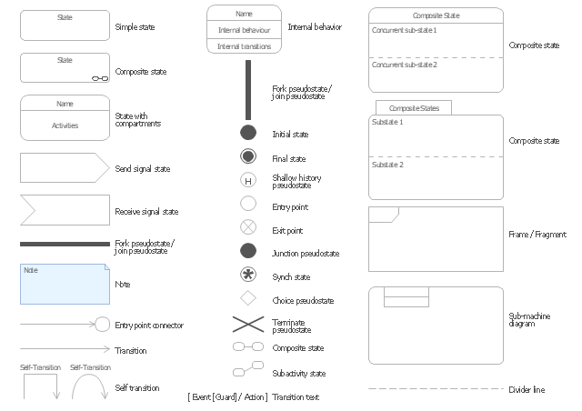
The vector stencils library "UML state machine diagrams" contains 35 symbols for the ConceptDraw PRO diagramming and vector drawing software.
"The state diagram in the Unified Modeling Language is essentially a Harel statechart with standardized notation, which can describe many systems, from computer programs to business processes. In UML 2 the name has been changed to State Machine Diagram. The following are the basic notational elements that can be used to make up a diagram:
(1) Filled circle, pointing to the initial state.
(2) Hollow circle containing a smaller filled circle, indicating the final state (if any).
(3) Rounded rectangle, denoting a state. Top of the rectangle contains a name of the state. Can contain a horizontal line in the middle, below which the activities that are done in that state are indicated.
(4) Arrow, denoting transition. The name of the event (if any) causing this transition labels the arrow body. A guard expression may be added before a "/ " and enclosed in square-brackets ( eventName[guardExpression] ), denoting that this expression must be true for the transition to take place. If an action is performed during this transition, it is added to the label following a "/ " ( eventName[guardExpression]/ action ).
(5) Thick horizontal line with either x>1 lines entering and 1 line leaving or 1 line entering and x>1 lines leaving. These denote join/ fork, respectively." [State diagram (UML). Wikipedia]
The example "Design elements - UML state machine diagrams" is included in the Rapid UML solution from the Software Development area of ConceptDraw Solution Park.
 Computer Network Diagrams
Computer Network Diagrams solution extends ConceptDraw PRO software with samples, templates and libraries of vector icons and objects of computer network devices and network components to help you create professional-looking Computer Network Diagrams, to plan simple home networks and complex computer network configurations for large buildings, to represent their schemes in a comprehensible graphical view, to document computer networks configurations, to depict the interactions between network's components, the used protocols and topologies, to represent physical and logical network structures, to compare visually different topologies and to depict their combinations, to represent in details the network structure with help of schemes, to study and analyze the network configurations, to communicate effectively to engineers, stakeholders and end-users, to track network working and troubleshoot, if necessary.
- Symbol With Meaning In Design Of Machine Element
- Design Of Machine Element All Symbol With Name
- Design Elements for UML Diagrams | Basic Flowchart Symbols and ...
- Design Of Machine Elements Symbol
- Symbols And Their Names In Design Of Machine Element
- Interior Design Machines and Equipment - Design Elements ...
- Design elements - UML state machine diagrams | Basic Flowchart ...
- Different Types Of Symbols In Design Of Machine Elements
- UML State Machine Diagram. Design Elements | Building Drawing ...
- UML State Machine Diagram. Design Elements | Interior Design ...
- Symbols Of Design Of Machines Elements
- Basic Flowchart Symbols and Meaning | Sales Steps | Name The ...
- Mechanical Drawing Symbols | Interior Design Machines and ...
- Design Of Machine Symbol
- UML State Machine Diagram. Design Elements | Design elements ...
- Symbol Used In Designing Machine Elements
- Useful Symbol In Machine Design
- Basic Flowchart Symbols and Meaning | Entity Relationship ...
- Interior Design Machines and Equipment - Design Elements ...
- How To use House Electrical Plan Software | Name And Symbols Of ...
