Network Diagram Software Backbone Network
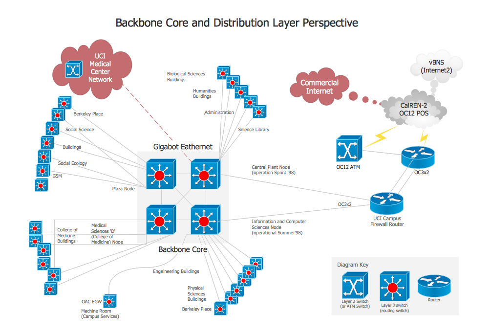
ConceptDraw - Perfect Network Diagramming Software with examples of Backbone Network Diagrams. ConceptDraw Network Diagram is ideal for network engineers and network designers who need to draw Backbone Network diagrams.
Network Printer
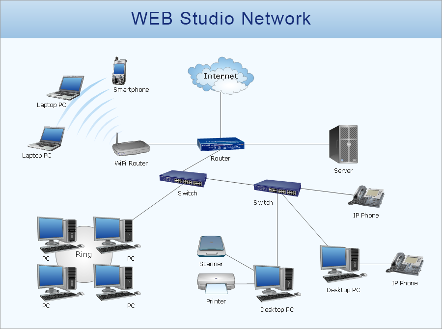
Special libraries of highly detailed, accurate shapes and computer graphics, servers, hubs, switches, printers, mainframes, face plates, routers etc.
HelpDesk
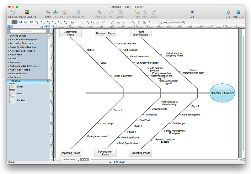
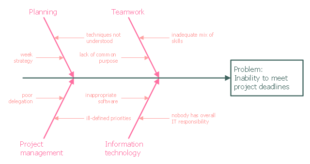
How to Draw a Fishbone Diagram with ConceptDraw PRO
Fishbone (Ishikawa) Diagram is often used in business to determine the cause of some problem. A Fishbone diagram is also called cause-and-effect diagram.The main goal of the Fishbone diagram is to illustrate in a graphical way the relationship between a given outcome and all the factors that influence this outcome. The complete diagram resembles a fish skeleton as its name implies. Cause and Effect analysis is used in management to identify the possible causes of a problem in order to eliminate them. The ability to create a Fishbone Diagram is supported by the Fishbone Diagram solution.Draw Network Diagram based on Templates and Examples
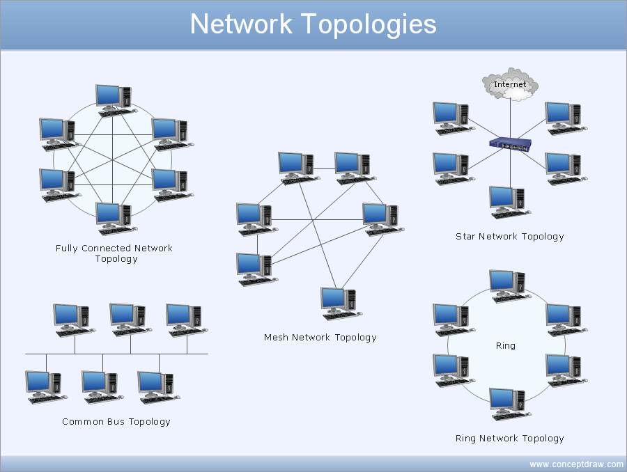
ConceptDraw is rapid and powerful network diagram drawing software with rich examples, templates, design objects and stencils.
This example was created on the base of the figure from the website of the Iowa State University Center for Excellence in Learning and Teaching.
"Fishbone.
What: The fishbone technique uses a visual organizer to identify the possible causes of a problem.
Benefits: This technique discourages partial or premature solutions and demonstrates the relative importance of, and interactions between, different parts of a problem.
How: On a broad sheet of paper, draw a long arrow horizontally across the middle of the page pointing to the right. Label the arrowhead with the title of the issue to be explained. This is the "backbone" of the "fish." Draw "spurs" from this "backbone" at about 45 degrees, one for every likely cause of the problem that the group can think of; and label each. Sub-spurs can represent subsidiary causes. The group considers each spur/ sub-spur, taking the simplest first, partly for clarity but also because a simple explanation may make more complex ones unnecessary. Ideally, the fishbone is redrawn so that position along the backbone reflects the relative importance of the different parts of the problem, with the most important at the head." [celt.iastate.edu/ creativity/ techniques.html]
The fishbone diagram example "Inability to meet project deadlines" was created using the ConceptDraw PRO diagramming and vector drawing software extended with the Fishbone Diagrams solution from the Management area of ConceptDraw Solution Park.
Design Element: Network Layout for Network Diagrams
ConceptDraw PRO is perfect for software designers and software developers who need to draw Network Layout Diagrams.
- Drow Diagram For Backbone Network Describe In Detail
- Draw Diagram For Backbone Network And Describe It In Detail
- Network Diagram Software Backbone Network | Mesh Network ...
- Network Diagram Software Backbone Network | Network Topologies ...
- How to Draw a Computer Network Diagrams | Network Diagram ...
- Network Diagram Software Backbone Network | Fishbone Diagram ...
- Network Printer | Network Diagram Software Backbone Network ...
- Network Diagram Software Backbone Network | Create Flow Chart ...
- Network Diagram Software Backbone Network | Hotel Network ...
- Network Diagram Software Backbone Network | Cisco Network ...
- Backbone Network Architecture Diagram
- Hotel Service Process | Network Diagram Software Backbone ...
- Network Diagram Software Backbone Network | How to Draw a ...
- Network Diagram Software Backbone Network | Metropolitan area ...
- Network Diagram Software Backbone Network | Network Topologies ...
- Telecommunication Network Diagrams | Network Diagram Software ...
- Network Diagram Software Backbone Network | Process Flowchart ...
- Network Diagram Software Backbone Network | Network Diagram ...
- Network Diagram Software Backbone Network | Computer Network ...
- Backbone Transmission Network With Diagram
.png)