HelpDesk
How to Create a Data Flow Diagram using ConceptDraw PRO
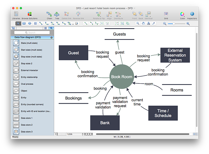
Data flow diagramming is a highly effective technique for showing the flow of information through a system. Data flow diagrams reveal relationships among and between the various components in a program or system. DFD is an important technique for modeling a system’s high-level detail by showing how input data is transformed to output results through a sequence of functional transformations. The set of standard symbols is used to depict how these components interact in a system. ConceptDraw PRO allows you to draw a simple and clear Data Flow Diagram using special libraries.- Data Flow Diagram Symbols . DFD Library | Basic Flowchart ...
- Data Flow Diagram ( DFD )
- Gane Sarson Diagram | DFD , Gane-Sarson notation - Vector stencils ...
- VGA connector pinout | Electrical Symbols , Electrical Diagram ...
- Basic Data Flow Diagram
- DFD Flowchart Symbols | How to Create a Data Flow Diagram using ...
- Entity Relationship Diagram Symbols | Basic Flowchart Symbols and ...
- Connector Usage In System Flow Diagram
- Basic Flowchart Symbols and Meaning | Data Flow Diagram ...
- Draw The Following Symbols In Data Flow Ii Connector
- What Are Connector Symbol
- Data Flow Diagram
- ERD Symbols and Meanings | Data Flow Diagram Symbols . DFD ...
- Dfd Symbol Using Standard Graphics Library Function Program
- Basic Flowchart Symbols and Meaning | Data Flow Diagram ...
- Data Flow Diagram Level 0 Definition
- Data Flow Diagram
- Data Flow Diagram Symbols . DFD Library | Example of DFD for ...
- Data Flow Diagram Rules And Symbols
