Data Flow Diagram Software

 Data Flow Diagrams (DFD)
Data Flow Diagrams solution extends ConceptDraw DIAGRAM software with templates, samples and libraries of vector stencils for drawing the data flow diagrams (DFD).
Data Flow Diagram (DFD)

Data Flow Diagram Symbols. DFD Library

Data Flow Diagram

 Windows 10 User Interface
Windows 10 User Interface solution extends significantly ConceptDraw DIAGRAM functionality with look-and-feel functions of GUI software and makes it a great assistant for Win10 designers, developers, and software engineers. This solution provides a wide s
Data Flow Diagrams

Data Flow Diagram Example

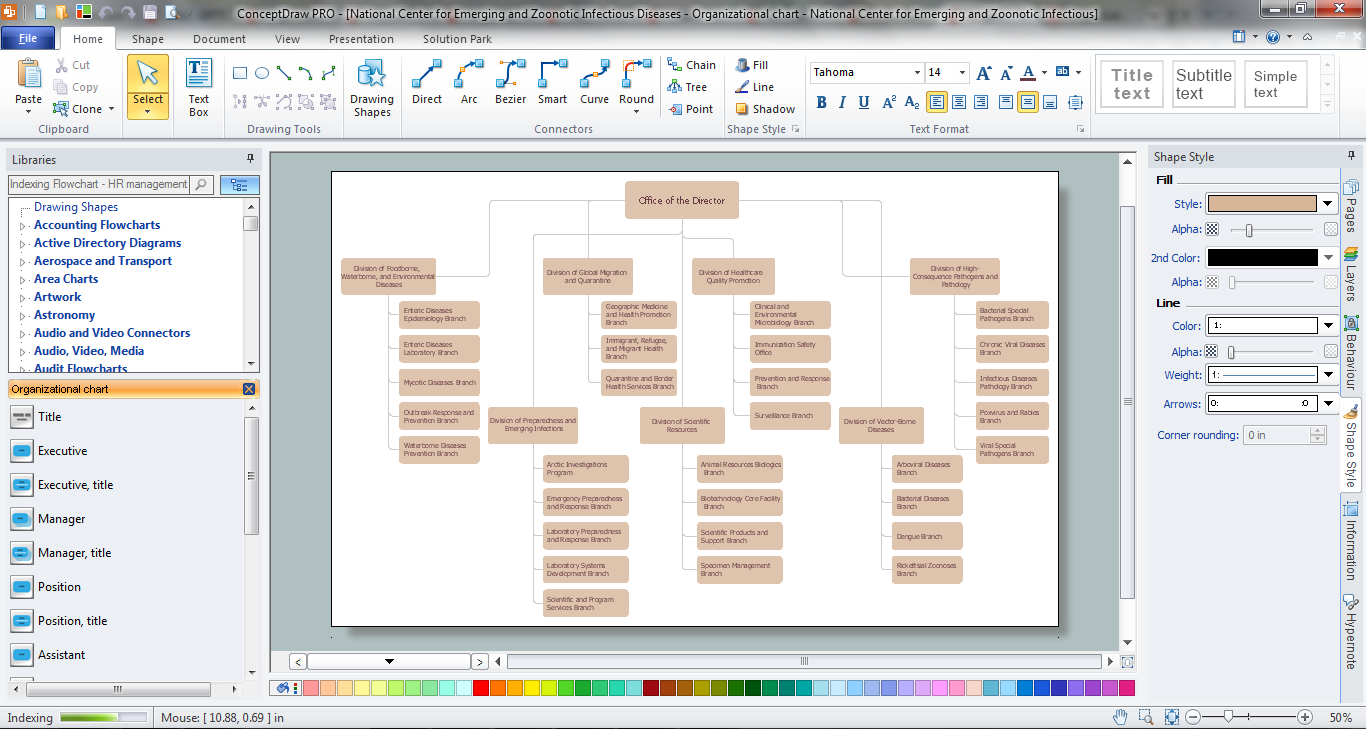
Orgchart
Entity Relationship Diagram - ERD - Software for Design Crows Foot ER Diagrams
_Win_Mac.png)

- Windows 10 User Interface | Dfd Drawing Software For Using Pc ...
- Standard Software For Dfd Drawing For Windows 10
- Windows 10 User Interface | Metro Map | 25 Typical Orgcharts | Dfd ...
- Wireless Networks | Computer Network Diagrams | Windows 10 ...
- Data Flow Diagrams ( DFD ) | Cross Functional Flowchart for ...
- IDEF Business Process Diagrams | GUI Prototyping with ...
- Windows 10 User Interface | Reflected Ceiling Plans | Online Tiles ...
- Data Flow Diagrams ( DFD ) | macOS User Interface | Interactive ...
- Example of DFD for Online Store ( Data Flow Diagram ) DFD ...