 SYSML
SYSML
The SysML solution helps to present diagrams using Systems Modeling Language; a perfect tool for system engineering.
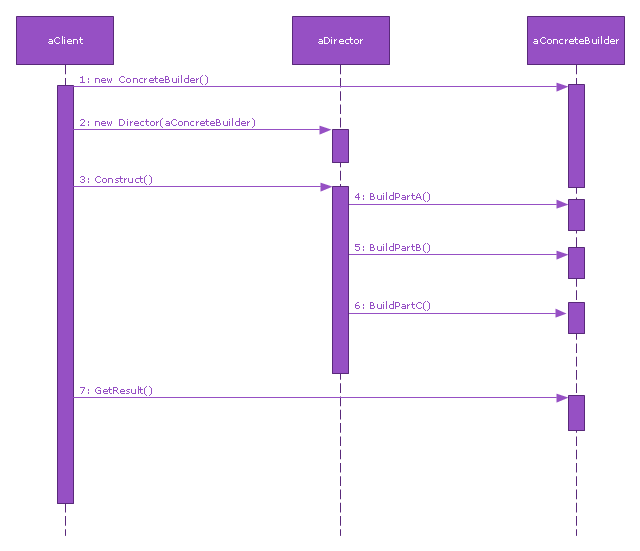
This sequence diagram example was redesigned from the Wikimedia Commons file: Builder design pattern sequence1.png.
"The UML sequence diagram which illustrates the Builder design pattern."
[commons.wikimedia.org/ wiki/ File:Builder_ design_ pattern_ sequence1.png]
"The builder pattern is an object creation software design pattern. Unlike the abstract factory pattern and the factory method pattern whose intention is to enable polymorphism, the intention of the builder pattern is to find a solution to the telescoping constructor anti-pattern. ... The intent of the Builder design pattern is to separate the construction of a complex object from its representation. By doing so the same construction process can create different representations." [Builder pattern. Wikipedia]
The SysML sequence diagram example "Builder design pattern sequence" was drawn using the ConceptDraw PRO diagramming and vector drawing software extended with the SysML solution from the Software Development area of ConceptDraw Solution Park.
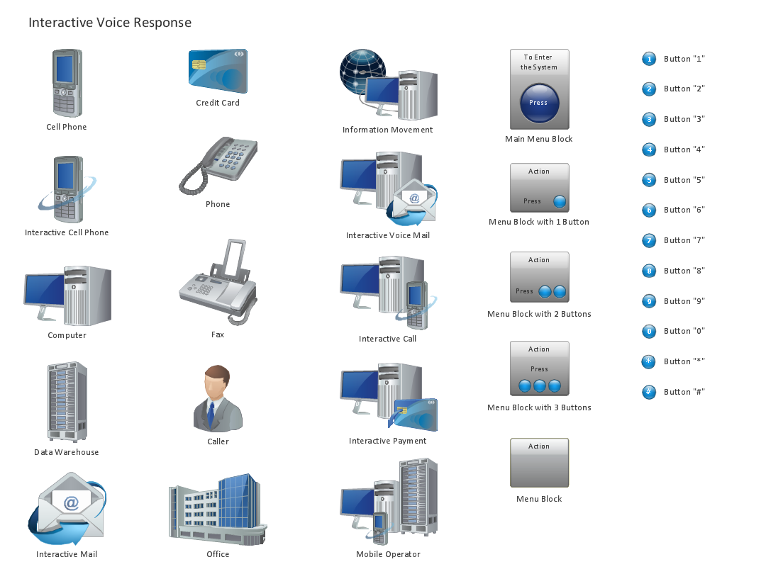
Design Element: IVR for Network Diagrams
ConceptDraw PRO is perfect for software designers and software developers who need to draw IVR Network Diagrams.
- How To create Diagrams for Amazon Web Services architecture ...
- How to Add a Bubble Diagram to a PowerPoint Presentation Using ...
- Uml Diagram Builder
- Use Case Diagram Builder
- Network Layout Floor Plans | Office Layout Plans | Examples of ...
- Design elements - ERD (crow's foot notation) | Entity Relationship ...
- Computer Network Diagrams | ConceptDraw PRO Network Diagram ...
- AWS Architecture Diagrams | Amazon Web Services Diagrams ...
- Logical network topology diagram | Network Topologies | Network ...
- Pyramid Diagram and Pyramid Chart | Pyramid Diagram | How to ...
- Interactive Voice Response Diagrams | Electric and Telecom Plans ...
- Telecommunication Network Diagrams | Process Flowchart ...
- Logical network topology diagram | Network Diagram Software ...
- Entity Relationship Diagram Software for Design Crows Foot ER ...
- Activity Network (PERT) Chart | Activity Network Diagram Method ...
- Circular diagrams - Vector stencils library | Rack diagrams - Vector ...
- Decision tree diagram | Influence Diagram Software | Decision ...
- Venn Diagrams | Venn Diagram | How to Create a Venn Diagram in ...
- Workflow Diagram Software Mac | Process Flowchart | HR ...
- UML Diagrams with ConceptDraw PRO | ConceptDraw Solution ...

