"The client–server model of computing is a distributed application structure that partitions tasks or workloads between the providers of a resource or service, called servers, and service requesters, called clients. Often clients and servers communicate over a computer network on separate hardware, but both client and server may reside in the same system. A server host runs one or more server programs which share their resources with clients. A client does not share any of its resources, but requests a server's content or service function. Clients therefore initiate communication sessions with servers which await incoming requests.
Examples of computer applications that use the client–server model are Email, network printing, and the World Wide Web." [Client–server model. Wikipedia]
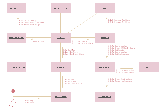
The UML communication diagram example "Client server access" was created using the ConceptDraw PRO diagramming and vector drawing software extended with the Rapid UML solution from the Software Development area of ConceptDraw Solution Park.
 Rapid UML
Rapid UML solution extends ConceptDraw PRO software with templates, samples and libraries of vector stencils for quick drawing the UML diagrams using Rapid Draw technology.
 Rapid UML
Rapid UML solution extends ConceptDraw PRO software with templates, samples and libraries of vector stencils for quick drawing the UML diagrams using Rapid Draw technology.
This example of cloud computing system architecture diagram was created on the base of picture in the post "Sending Windows 8 Push Notifications using Windows Azure Mobile Services" from the Nick Harris .NET blog.
"The goal of Windows Azure Mobile Services is to make it incredibly easy for developers to add a cloud backend to their client apps be it a Windows 8, Windows Phone, iOS or Android application. ... Mobile Services today provides:
- Structured Storage
- Server Logic ...
- Auth ...
- Push Notifications ...
- Common tenants of Windows Azure Services
- Scale ...
- Diagnostics ...
- Logging ...
What are Push Notifications?
The Windows Push Notification Services (WNS) enables you to send toast, tile, badge and raw notifications from the cloud to your Windows Store applications even when your app is not running. Push notifications are ideal for scenarios when you need to target a specific user with personalized content.
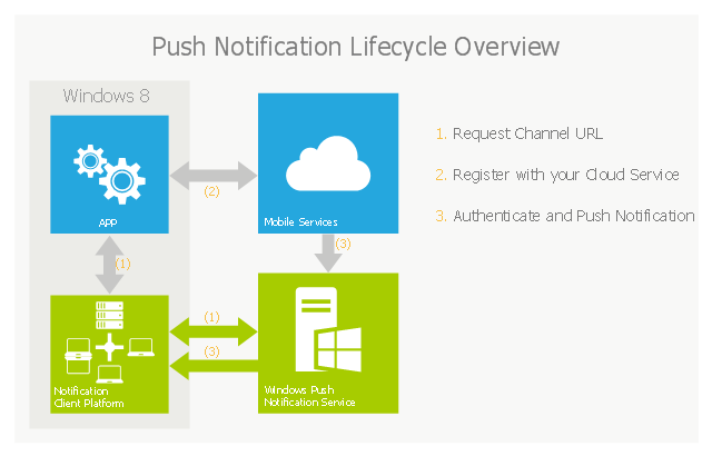
The following diagram depicts the general Lifecycle of a push notifications via the Windows Azure Notification Service (WNS). We’ll walk through the steps shortly but before doing so I thought it would be important to call out that as a developer implementing a push notification scenario all you need to do is implement those interactions in grey and the applications/ services in blue." [nickharris.net/ index.php/ 2012/ 10/ 04/ blog-series-sending-windows-8-push-notifications-using-windows-azure-mobile-services/ ]
The diagram example "Push Notification Lifecycle Overview" was created using ConceptDraw PRO diagramming and vector drawing software extended with the Azure Architecture solution from the Computer and Networks area of ConceptDraw Solution Park.
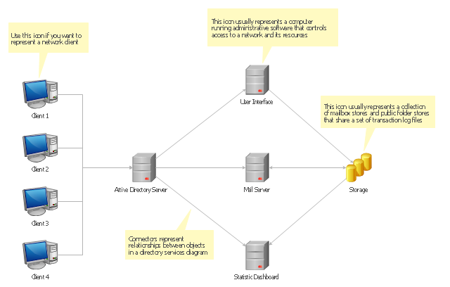
Active Directory Diagrams visualize the detail structures of the Microsoft Windows networks, Active Directory Domain topology, the Active Directory Site topology, the Organizational Units (OU), and the Exchange Server Organization. They are used to visually document the Microsoft Active Directory network detail structure for network designing, and for managing the control access to printers and files, the access and security, the traffic flow optimization in local and wide area nets, the network equipment maintenance and repair, the data backup, storage, and recovery.
The Active Directory diagram template for the ConceptDraw PRO diagramming and vector drawing software is included in the Active Directory Diagrams solution from the Computer and Networks area of ConceptDraw Solution Park.
The Active Directory diagram template for the ConceptDraw PRO diagramming and vector drawing software is included in the Active Directory Diagrams solution from the Computer and Networks area of ConceptDraw Solution Park.
This exaple was resigned from the Wikimedia Commons file: Mobile Cloud Architecture.jpg. [commons.wikimedia.org/ wiki/ File:Mobile_ Cloud_ Architecture.jpg]
This file is licensed under the Creative Commons Attribution-Share Alike 3.0 Unported license. [creativecommons.org/ licenses/ by-sa/ 3.0/ deed.en]
This diagram describes general architecture of Mobile Cloud Computing.
Legend.
BTS: Base Transceiver Station.
AAA: Network Authentication, Authorization, and Accounting.
HA: Home Agent.
"Mobile/ cloud computing is the combination of cloud computing and mobile networks to bring benefits for mobile users, network operators, as well as cloud computing providers. The ultimate goal of MCC (mean of MCC is Mobile/ Cloud Computing) is to enable execution of rich mobile applications on a plethora of mobile devices, with a rich user experience. MCC provides business opportunities for mobile network operators as well as cloud providers." [Mobile cloud computing. Wikipedia]
The example "Mobile cloud architecture diagram" was created using the ConceptDraw PRO diagramming and vector drawing software extended with the AWS Architecture Diagrams solution from the Computer and Networks area of ConceptDraw Solution Park.
"Request methods.
An HTTP 1.1 request made using telnet. The request, response headers and response body are highlighted.
HTTP defines methods (sometimes referred to as verbs) to indicate the desired action to be performed on the identified resource. What this resource represents, whether pre-existing data or data that is generated dynamically, depends on the implementation of the server. Often, the resource corresponds to a file or the output of an executable residing on the server. The HTTP/ 1.0 specification:section 8 defined the GET, POST and HEAD methods and the HTTP/ 1.1 specification:section 9 added 5 new methods: OPTIONS, PUT, DELETE, TRACE and CONNECT. By being specified in these documents their semantics are well known and can be depended upon. Any client can use any method and the server can be configured to support any combination of methods. If a method is unknown to an intermediate it will be treated as an unsafe and non-idempotent method. There is no limit to the number of methods that can be defined and this allows for future methods to be specified without breaking existing infrastructure. For example, WebDAV defined 7 new methods and RFC5789 specified the PATCH method.
GET.
Requests a representation of the specified resource. Requests using GET should only retrieve data and should have no other effect. (This is also true of some other HTTP methods.)" [Hypertext Transfer Protocol. Wikipedia]
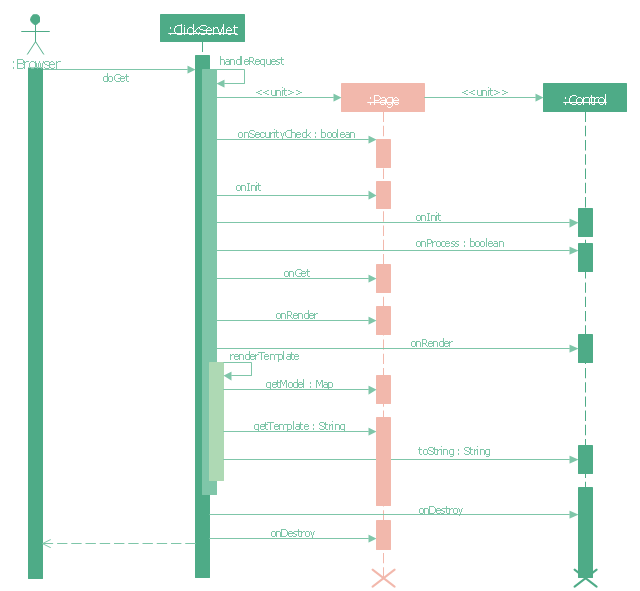
The UML sequence diagram example "GET request" was created using the ConceptDraw PRO diagramming and vector drawing software extended with the Rapid UML solution from the Software Development area of ConceptDraw Solution Park.
 Rack Diagrams
Rack Diagrams solution extends ConceptDraw PRO software with samples, templates and libraries of vector stencils for drawing the computer network server rack mounting diagrams.
Network Diagram Software Logical Network Diagram
Perfect Network Diagramming Software with examples of LAN Diagrams. ConceptDraw Network Diagram is ideal for network engineers and network designers who need to draw Logical Network diagrams.
- Uml Diagram For Email Client Server System
- UML communication diagram - Client server access | Diagramming ...
- UML component diagram - Start server | UML communication ...
- Uml Diagram For Client Server Program
- UML communication diagram - Client server access | Campus Area ...
- How To Draw Collaboration Diagram For Client Server
- UML communication diagram - Client server access | Cloud round ...
- Email Client System Uml Diagrams
- Client Server Network Diagram
- Design Diagram Client Server
- UML communication diagram - Client server access | UML ...
- Activity Diagram For Client Server Communication
- UML communication diagram - Client server access | Star Network ...
- UML communication diagram - Client server access | Diagramming ...
- Objects Diagram For Client Systems And Server
- Collaboration Diagram For E Mail Server
- UML communication diagram - Client server access | Basic ...
- Use Case Diagram For Mail Server
- UML communication diagram - Client server access
- Server | Server hardware - Rack diagram | UML component diagram ...


