"A help desk is a resource intended to provide the customer or end user with information and support related to a company's or institution's products and services. The purpose of a help desk is usually to troubleshoot problems or provide guidance about products such as computers, electronic equipment, food, apparel, or software. Corporations usually provide help desk support to their customers through various channels such as toll-free numbers, websites, instant messaging, or email. There are also in-house help desks designed to provide assistance to employees." [Help desk. Wikipedia]
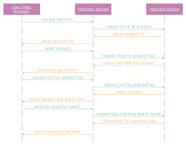
The UML sequence diagram example "Help desk" was created using the ConceptDraw PRO diagramming and vector drawing software extended with the Rapid UML solution from the Software Development area of ConceptDraw Solution Park.
The UML sequence diagram example "Help desk" was created using the ConceptDraw PRO diagramming and vector drawing software extended with the Rapid UML solution from the Software Development area of ConceptDraw Solution Park.
UML sequence diagram
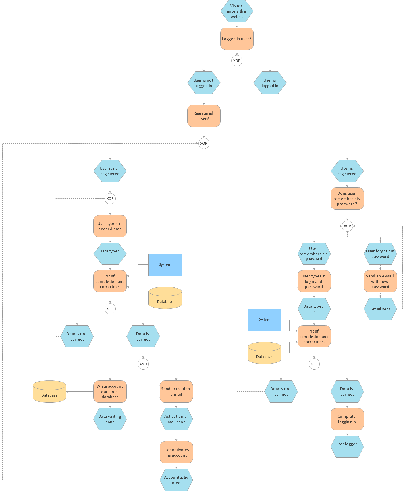
Process Flowchart


Bubble diagrams in Landscape Design with ConceptDraw DIAGRAM

UML Diagram

Block Diagram

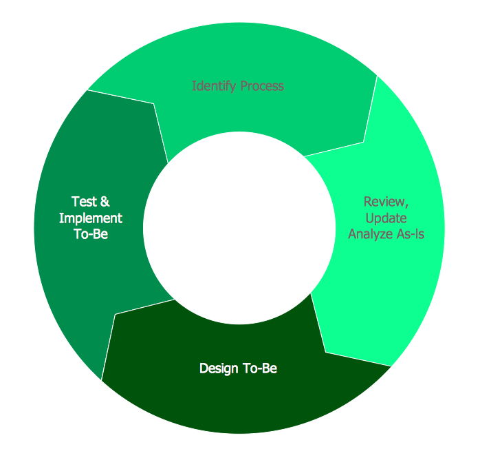
BPR Diagram. Business Process Reengineering Example
How to Help Customers be More Productive
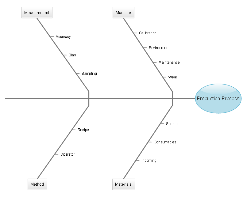
How Do Fishbone Diagrams Solve Manufacturing Problems

Fishbone Diagram
How to Draw a Computer Network Diagrams

- Computer Network Diagrams | Network Diagramming with ...
- Explain Accounting Cycle Help Diagram And Examples
- With The Help Of The Diagram Show The Link Between The Basic
- Uml Diagram Help
- Collaboration Diagram Uml For Help Desk
- With The Help Of A Diagram Explain Porter's Generic Strategies
- Accounting Flowcharts | With Help Diagram Explain Several Steps ...
- Explain The Circular Flow Of Communication With The Help Of A ...
- Garrett IA Diagrams with ConceptDraw PRO | With The Help Of A ...
- UML sequence diagram - Help desk