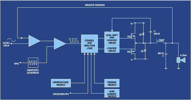
The circuit diagram example "Amplifier" was redesigned from the Wikimedia Commons file: Slika br.5.JPG.
[commons.wikimedia.org/ wiki/ File:Slika_ br.5.JPG]
This file is made available under the Creative Commons CC0 1.0 Universal Public Domain Dedication. [creativecommons.org/ publicdomain/ zero/ 1.0/ deed.en]
"An electronic amplifier, amplifier, or (informally) amp is an electronic device that increases the power of a signal. It does this by taking energy from a power supply and controlling the output to match the input signal shape but with a larger amplitude. In this sense, an amplifier modulates the output of the power supply.
There are four basic types of electronic amplifier: the voltage amplifier, the current amplifier, the transconductance amplifier, and the transresistance amplifier. A further distinction is whether the output is a linear or nonlinear representation of the input. Amplifiers can also be categorized by their physical placement in the signal chain." [Amplifier. Wikipedia]
The circuit diagram example "Amplifier" was created using the ConceptDraw PRO diagramming and vector drawing software extended with the Electrical Engineering solution from the Engineering area of ConceptDraw Solution Park.
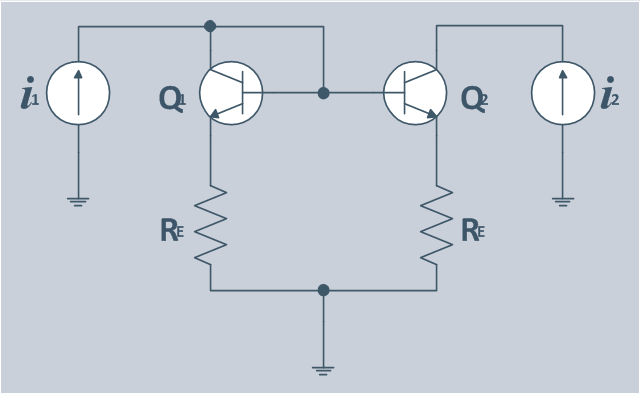
The circuit diagram example "Bipolar current mirror" was redesigned from the Wikipedia file: Current mirror.png.
[en.wikipedia.org/ wiki/ File:Current_ mirror.png]
This file is licensed under the Creative Commons Attribution-Share Alike 3.0 Unported license. [creativecommons.org/ licenses/ by-sa/ 3.0/ deed.en]
"A current mirror is a circuit designed to copy a current through one active device by controlling the current in another active device of a circuit, keeping the output current constant regardless of loading. The current being 'copied' can be, and sometimes is, a varying signal current. Conceptually, an ideal current mirror is simply an ideal inverting current amplifier that reverses the current direction as well or it is a current-controlled current source (CCCS). The current mirror is used to provide bias currents and active loads to circuits. ...
Basic BJT current mirror.
If a voltage is applied to the BJT base-emitter junction as an input quantity and the collector current is taken as an output quantity, the transistor will act as an exponential voltage-to-current converter. By applying a negative feedback (simply joining the base and collector) the transistor can be "reversed" and it will begin acting as the opposite logarithmic current-to-voltage converter; now it will adjust the "output" base-emitter voltage so as to pass the applied "input" collector current.
The simplest bipolar current mirror ... implements this idea. It consists of two cascaded transistor stages acting accordingly as a reversed and direct voltage-to-current converters." [Current mirror. Wikipedia]
The circuit diagram example "Bipolar current mirror" was created using the ConceptDraw PRO diagramming and vector drawing software extended with the Electrical Engineering solution from the Engineering area of ConceptDraw Solution Park.
"In electronics, a vacuum tube, electron tube (in North America), tube, or thermionic valve or valve (in British English) is a device controlling electric current through a vacuum in a sealed container. The simplest vacuum tube, the diode, contains only two elements; current can only flow in one direction through the device between the two electrodes, as electrons emitted by the hot cathode travel through the tube and are collected by the anode. Addition of a third and additional electrodes allows the current flowing between cathode and anode to be controlled in various ways. The device can be used as an electronic amplifier, a rectifier, an electronically controlled switch, an oscillator, and for other purposes.
Vacuum tubes mostly rely on thermionic emission of electrons from a hot filament or a cathode heated by the filament. Some electron tube devices rely on the properties of a discharge through an ionized gas." [Vacuum tube. Wikipedia]
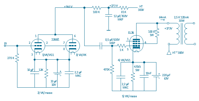
"The EL34 is a thermionic valve or vacuum tube of the power pentode type. It has an international octal base (indicated by the '3' in the part number) and is found mainly in the final output stages of audio amplification circuits and was designed to be suitable as a series regulator by virtue of its high permissible voltage between heater and cathode and other parameters. The American RETMA tube designation number for this tube is 6CA7. Russian analog is 6P27S (Cyrillic: 6П27C )" [EL34. Wikipedia]
This circuit diagram sample was redrawn from the Wikipedia Commons file: EL34 schematics (circuit diagram).gif. [commons.wikimedia.org/ wiki/ File:EL34_ schematics_ %28circuit_ diagram%29.gif]
The example "Circuit diagram - EL 34 schematics" was drawn using the ConceptDraw PRO diagramming and vector drawing software extended with the Electrical Engineering solution from the Engineering area of ConceptDraw Solution Park.
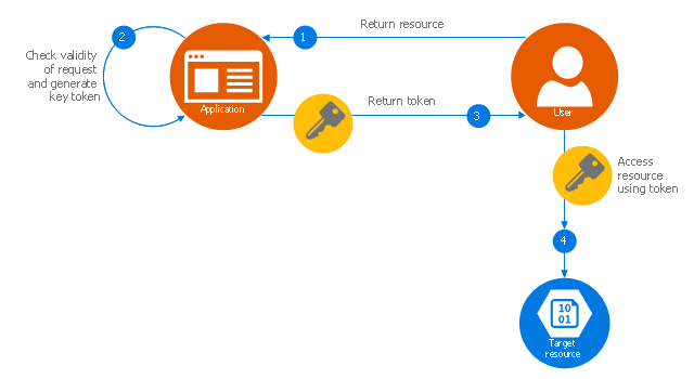
This Azure cloud architecture pattern diagram template was created on the base of figure in the article "Valet Key Pattern" from the Microsoft Developer Network (MSDN) website.
"Valet Key Pattern.
Use a token or key that provides clients with restricted direct access to a specific resource or service in order to offload data transfer operations from the application code. This pattern is particularly useful in applications that use cloud-hosted storage systems or queues, and can minimize cost and maximize scalability and performance. ...
Client programs and web browsers often need to read and write files or data streams to and from an application’s storage. ...
Data stores have the capability to handle upload and download of data directly, without requiring the application to perform any processing to move this data, but this typically requires the client to have access to the security credentials for the store.
... applications must be able to securely control access to data in a granular way, but still reduce the load on the server by setting up this connection and then allowing the client to communicate directly with the data store to perform the required read or write operations. ...
To resolve the problem of controlling access to a data store where the store itself cannot manage authentication and authorization of clients, one typical solution is to restrict access to the data store’s public connection and provide the client with a key or token that the data store itself can validate.
This key or token is usually referred to as a valet key. It provides time-limited access to specific resources and allows only predefined operations such as reading and writing to storage or queues, or uploading and downloading in a web browser. Applications can create and issue valet keys to client devices and web browsers quickly and easily, allowing clients to perform the required operations without requiring the application to directly handle the data transfer. This removes the processing overhead, and the consequent impact on performance and scalability, from the application and the server." [msdn.microsoft.com/ ru-RU/ library/ dn568102.aspx]
The Azure cloud system architecture diagram template "Valet key pattern" for the ConceptDraw PRO diagramming and vector drawing software is included in the Azure Architecture solutin from the Computer and Networks area of ConceptDraw Solution Park.
HelpDesk
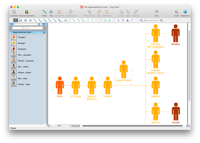
How to Draw a Flat Organizational Chart with ConceptDraw PRO
A clear organizational chart helps you to understand the relationships of positions in an organization in terms of authority and responsibility. A Flat organizational structure is one of the most typical organizational structure. Use The Flat Organizational chart template to draw an organizational structure of your company. ConceptDraw 25 Typical Orgcharts solution provides you with the possibility to develop typical organizational charts quickly and easily.Think. Act. Accomplish.
ConceptDraw MINDMAP is ready to provide you with mind mapping tool which can serve as comprehensive productivity tool for your business.The vector stencils library Initiation and annunciation contains 9 symbols of Fire Alarm Control Panel (FACP) or Fire Alarm Control Unit (FACU) elements, triggering devices, audible alarm systems, timers, security control equipment, and recording devices.
"A Fire Alarm Control Panel (FACP), or Fire Alarm Control Unit (FACU), is the controlling component of a Fire Alarm System. The panel receives information from environmental sensors designed to detect changes associated with fire, monitors their operational integrity and provides for automatic control of equipment, and transmission of information necessary to prepare the facility for fire based on a predetermined sequence. The panel may also supply electrical energy to operate any associated sensor, control, transmitter, or relay. There are four basic types of panels: coded panels, conventional panels, addressable panels, and multiplex systems." [Fire alarm control panel. Wikipedia]
Use the shapes library Initiation and annunciation to draw layout floor plans, communications schematics and wiring diagrams of security systems using the ConceptDraw PRO diagramming and vector drawing software.
The design elements library Initiation and annunciation is included in the Security and Access Plans solution from the Building Plans area of ConceptDraw Solution Park.
The vector stencils library "Cybersecurity clipart" contains 197 computer security icons.
Use it to design your computer security diagrams and cybersecurity infographics with ConceptDraw PRO software.
"Computer security, also known as cybersecurity or IT security, is the protection of information systems from theft or damage to the hardware, the software, and to the information on them, as well as from disruption or misdirection of the services they provide. It includes controlling physical access to the hardware, as well as protecting against harm that may come via network access, data and code injection, and due to malpractice by operators, whether intentional, accidental, or due to them being tricked into deviating from secure procedures." [Computer security. Wikipedia]
The icon set example "Design elements - Cybersecurity clipart" is included in the Network Security Diagrams solution from the Computer and Networks area of ConceptDraw Solution Park.
- Process Flowchart | Layout Diagram Of Controlling Lamp From ...
- What Is An Axial Controlling Diagram
- How To Create CCTV Network Diagram | Security and Access Plans ...
- Business Controlling Process With The Help Of Flow Chart
- Lighting and switch layout
- Control Symbols And Units
- How To use House Electrical Plan Software | Electrical Symbols ...
- Stations - Vector stencils library | Electrical Symbols, Electrical ...
- Process Flowchart | Data Flow Diagram | How to Create Flowcharts ...
- Software Work Flow Process in Project Management with Diagram ...
- Amplifier - Circuit diagram | Bipolar current mirror - Circuit diagram ...
- Process Flowchart | Project management life cycle - Flowchart ...
- Flow Chart Of Controlling Process
- Cisco ISG - Network topology diagram
- Four Floor Wiring Diagram
- Types of Flowchart - Overview | Process Flowchart | Project ...
- Bipolar current mirror - Circuit diagram | Amplifier - Circuit diagram ...
- Electrical Symbols, Electrical Diagram Symbols | Design elements ...
- Simple switched supply - Circuit diagram | Electrical Drawing ...
- Symbol For Control Unit
