Network Layout


Network Diagramming Software for Design Network Layout Diagrams
_Win_Mac.png "Network Diagramming Software, Design Elements - Network Layout (Windows, Macintosh)")
How To Create Restaurant Floor Plan in Minutes


 ConceptDraw Solution Park
ConceptDraw Solution Park collects graphic extensions, examples and learning materials
 Interactive Voice Response Diagrams
Interactive Voice Response Diagrams solution extends ConceptDraw PRO v10 software with samples, templates and libraries of ready-to-use vector stencils that help create Interactive Voice Response (IVR) diagrams illustrating in details a work of interactive voice response system, the IVR system’s logical and physical structure, Voice-over-Internet Protocol (VoIP) diagrams, and Action VoIP diagrams with representing voice actions on them, to visualize how the computers interact with callers through voice recognition and dual-tone multi-frequency signaling (DTMF) keypad inputs.
HelpDesk
How to Create a CCTV Diagram in ConceptDraw PRO

Office Layout


Building Drawing Software for Design Office Layout Plan

 Network Layout Floor Plans
Network Layout Floor Plans solution extends ConceptDraw PRO software functionality with powerful tools for quick and efficient documentation the network equipment and displaying its location on the professionally designed Network Layout Floor Plans. Never before creation of Network Layout Floor Plans, Network Communication Plans, Network Topologies Plans and Network Topology Maps was not so easy, convenient and fast as with predesigned templates, samples, examples and comprehensive set of vector design elements included to the Network Layout Floor Plans solution. All listed types of plans will be a good support for the future correct cabling and installation of network equipment.
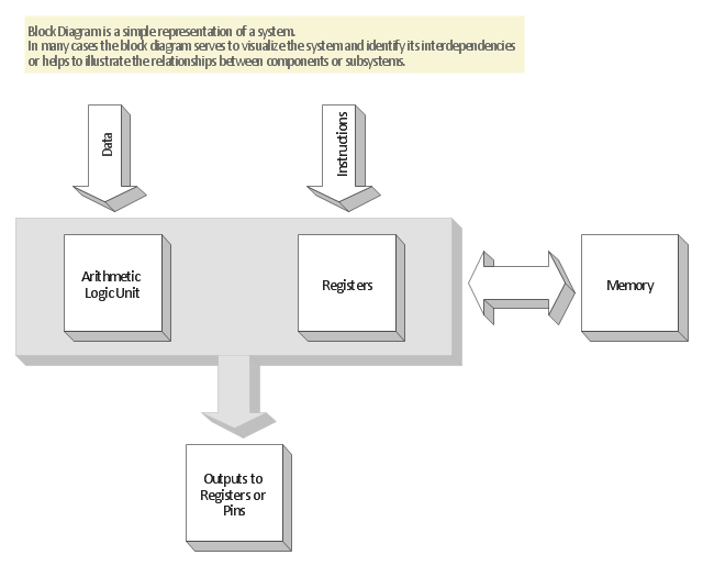
"The block diagram is typically used for a higher level, less detailed description aimed more at understanding the overall concepts and less at understanding the details of implementation. Contrast this with the schematic diagram and layout diagram used in the electrical engineering world, where the schematic diagram shows the details of each electrical component and the layout diagram shows the details of physical construction." [Block diagram. Wikipedia]
The 3D block diagram template for the ConceptDraw PRO diagramming and vector drawing software is included in the Block Diagrams solution from the area "What is a Diagram" of ConceptDraw Solution Park.
The 3D block diagram template for the ConceptDraw PRO diagramming and vector drawing software is included in the Block Diagrams solution from the area "What is a Diagram" of ConceptDraw Solution Park.
3D Block diagram template
 Plant Layout Plans
This solution extends ConceptDraw PRO v.9.5 plant layout software (or later) with process plant layout and piping design samples, templates and libraries of vector stencils for drawing Plant Layout plans. Use it to develop plant layouts, power plant desig
 Office Layout Plans
Office layouts and office plans are a special category of building plans and are often an obligatory requirement for precise and correct construction, design and exploitation office premises and business buildings. Designers and architects strive to make office plans and office floor plans simple and accurate, but at the same time unique, elegant, creative, and even extraordinary to easily increase the effectiveness of the work while attracting a large number of clients.
Network Diagramming Software for Design Rack Diagrams
_Win_Mac.png "Network Diagramming Software, Design Elements — Network Layout (Windows, Macintosh)")
How To Draw Building Plans

 Telecommunication Network Diagrams
Telecommunication Network Diagrams solution extends ConceptDraw PRO software with samples, templates, and great collection of vector stencils to help the specialists in a field of networks and telecommunications, as well as other users to create Computer systems networking and Telecommunication network diagrams for various fields, to organize the work of call centers, to design the GPRS networks and GPS navigational systems, mobile, satellite and hybrid communication networks, to construct the mobile TV networks and wireless broadband networks.
 Computer Network Diagrams
Computer Network Diagrams solution extends ConceptDraw PRO software with samples, templates and libraries of vector icons and objects of computer network devices and network components to help you create professional-looking Computer Network Diagrams, to plan simple home networks and complex computer network configurations for large buildings, to represent their schemes in a comprehensible graphical view, to document computer networks configurations, to depict the interactions between network's components, the used protocols and topologies, to represent physical and logical network structures, to compare visually different topologies and to depict their combinations, to represent in details the network structure with help of schemes, to study and analyze the network configurations, to communicate effectively to engineers, stakeholders and end-users, to track network working and troubleshoot, if necessary.
 Target and Circular Diagrams
This solution extends ConceptDraw PRO software with samples, templates and library of design elements for drawing the Target and Circular Diagrams.
- Electrical Drawing Software | How To use House Electrical Plan ...
- Wireless broadband network layout diagram | Telecommunication ...
- UML Composite Structure Diagram
- Design Element: Network Layout for Network Diagrams | Basic ...
- Cisco Network Templates | Network Diagram Examples | Network ...
- Network Diagram Examples | Network Architecture | Network Layout ...
- Wireless broadband network layout diagram
- Network floor plan layout
- Network Diagramming Software for Design Network Layout Diagrams
- Network Diagramming Software for Design Rack Diagrams | Rack ...
- Network Diagram Examples | Network Diagram Software | Wireless ...
- How To Draw Building Plans | Network Diagram Examples | Network ...
- Network Architecture | Network Diagramming Software for Design ...
- Network Diagram Examples | Network Layout | Network Layout Floor ...
- Network Layout | Network Diagramming Software for Design ...
- Computer network diagram | Wireless broadband network layout ...
- Bubble diagrams in Landscape Design with ConceptDraw PRO ...
- Network Layout | Network Diagram Software Topology Network ...
- Network floor plan layout
- Network Layout | Network Diagram Examples | Network Architecture |