Electrical Symbols — Resistors

Electrical Diagram Software


Electrical Symbols, Electrical Diagram Symbols

The vector stencils library "Logic gate diagram" contains 17 element symbols for drawing the logic gate diagrams.
"To build a functionally complete logic system, relays, valves (vacuum tubes), or transistors can be used. The simplest family of logic gates using bipolar transistors is called resistor-transistor logic (RTL). Unlike simple diode logic gates (which do not have a gain element), RTL gates can be cascaded indefinitely to produce more complex logic functions. RTL gates were used in early integrated circuits. For higher speed and better density, the resistors used in RTL were replaced by diodes resulting in diode-transistor logic (DTL). Transistor-transistor logic (TTL) then supplanted DTL. As integrated circuits became more complex, bipolar transistors were replaced with smaller field-effect transistors (MOSFETs); see PMOS and NMOS. To reduce power consumption still further, most contemporary chip implementations of digital systems now use CMOS logic. CMOS uses complementary (both n-channel and p-channel) MOSFET devices to achieve a high speed with low power dissipation." [Logic gate. Wikipedia]
The symbols example "Design elements - Logic gate diagram" was drawn using the ConceptDraw PRO diagramming and vector drawing software extended with the Electrical Engineering solution from the Engineering area of ConceptDraw Solution Park.
Logic gate symbols

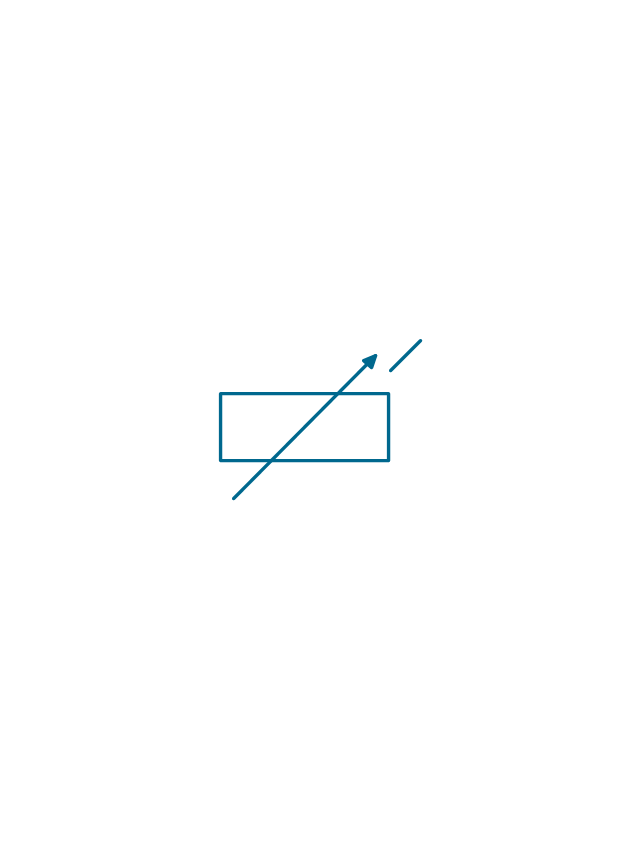
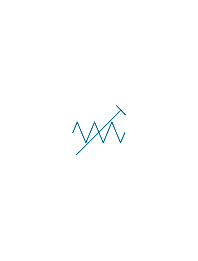
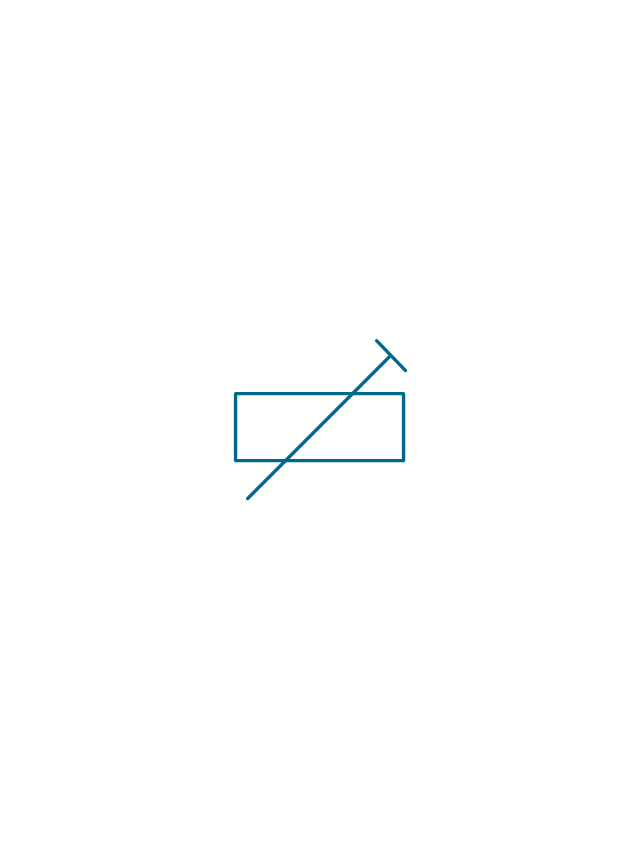
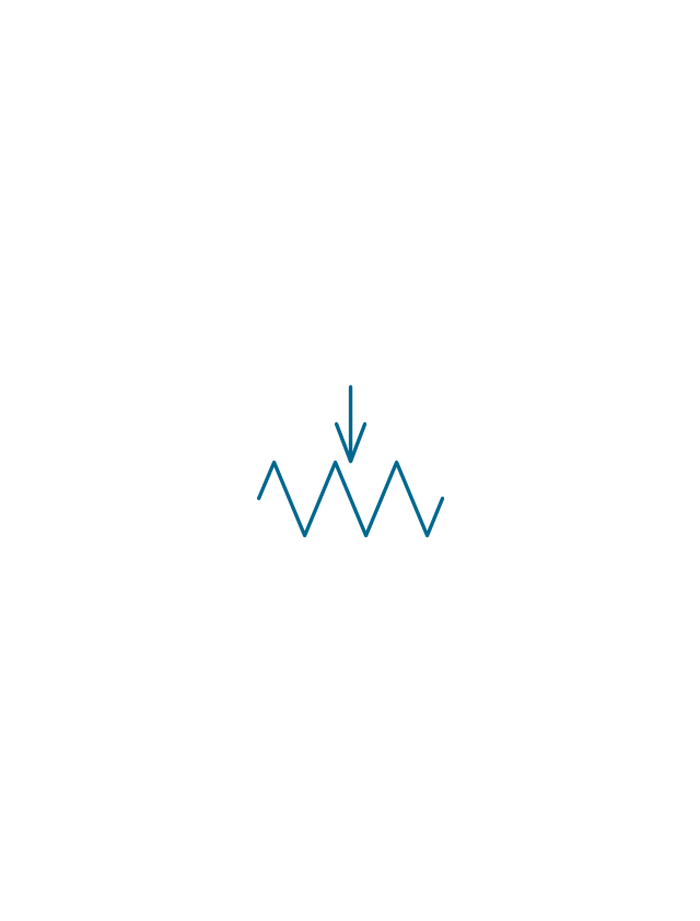
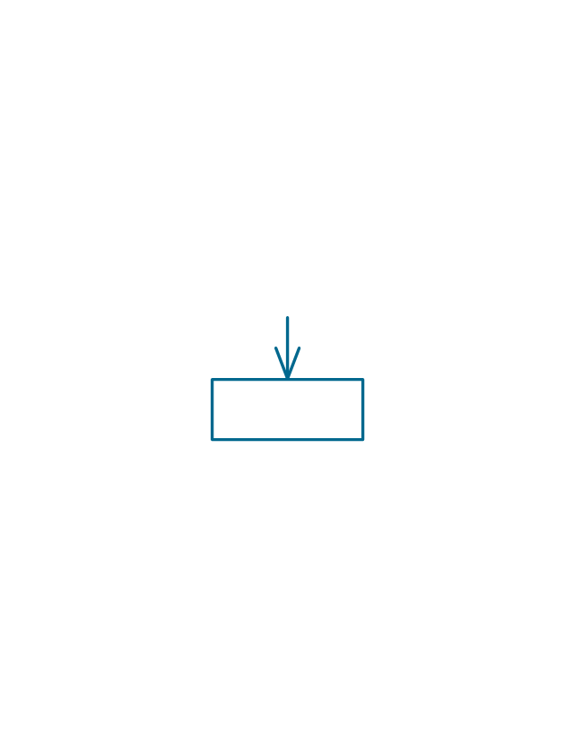
The vector stencils library "Resistors" contains 14 element symbols of resistors for drawing electronic schematics, circuit diagrams and electrical drawings.
"A resistor is a passive two-terminal electrical component that implements electrical resistance as a circuit element. Resistors act to reduce current flow, and, at the same time, act to lower voltage levels within circuits. Resistors may have fixed resistances or variable resistances, such as those found in thermistors, varistors, trimmers, photoresistors and potentiometers.
The current through a resistor is in direct proportion to the voltage across the resistor's terminals. This relationship is represented by Ohm's law ...
Resistors are common elements of electrical networks and electronic circuits and are ubiquitous in electronic equipment. Practical resistors can be composed of various compounds and films, as well as resistance wires (wire made of a high-resistivity alloy, such as nickel-chrome). Resistors are also implemented within integrated circuits, particularly analog devices, and can also be integrated into hybrid and printed circuits." [Resistor. Wikipedia]
The shapes example "Design elements - Resistors" was drawn using the ConceptDraw PRO diagramming and vector drawing software extended with the Electrical Engineering solution from the Engineering area of ConceptDraw Solution Park.
Resistor symbols

Electrical Diagram

The vector stencils library "Resistors" contains 14 element symbols of resistors.
Use these shapes for drawing electronic schematics, circuit diagrams and electrical drawings in the ConceptDraw PRO diagramming and vector drawing software extended with the Electrical Engineering solution from the Engineering area of ConceptDraw Solution Park.
www.conceptdraw.com/ solution-park/ engineering-electrical
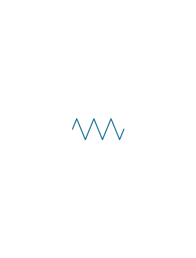
Resistor

Resistor
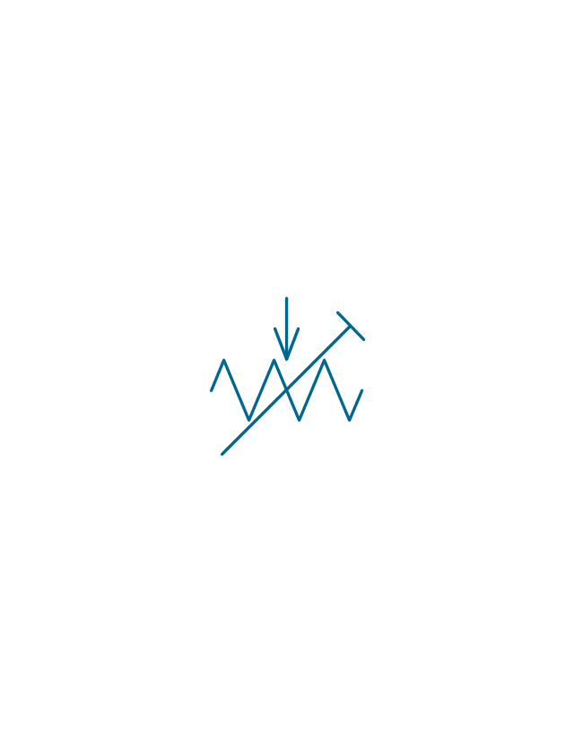
Variable resistor
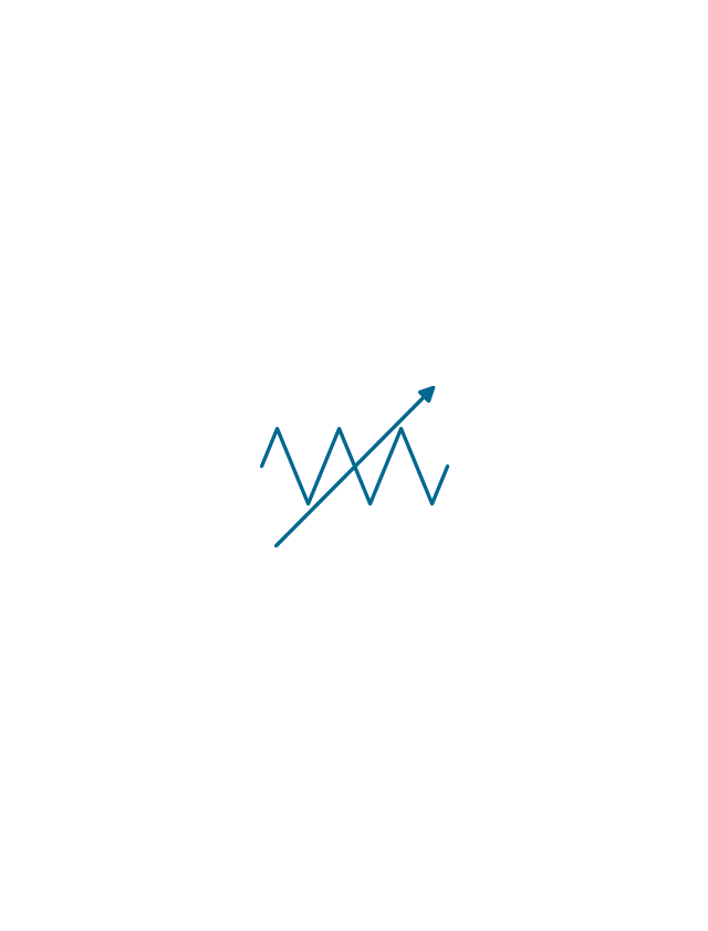
Variable resistor
Continuous resistor
Continuous resistor
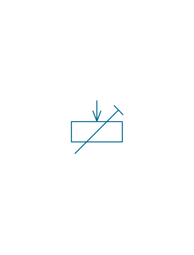
Pre-set resistor
Pre-set resistor
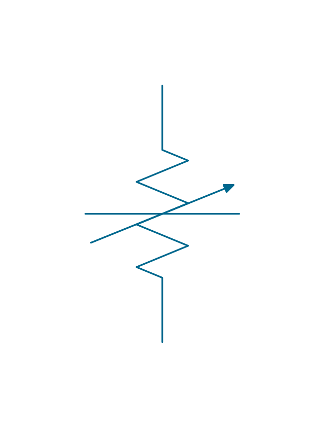
Potentiometer
Potentiometer
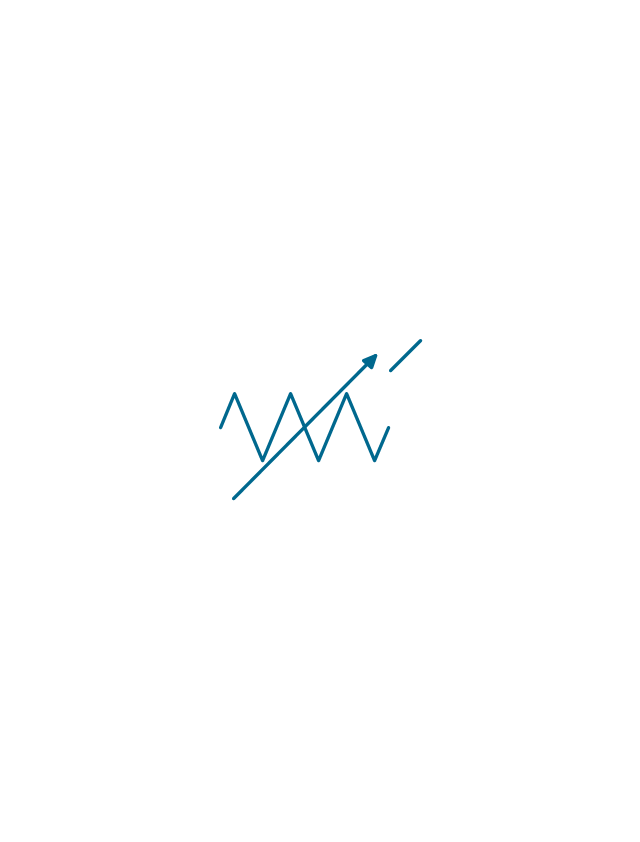
Pre-set potentiometer
Pre-set potentiometer
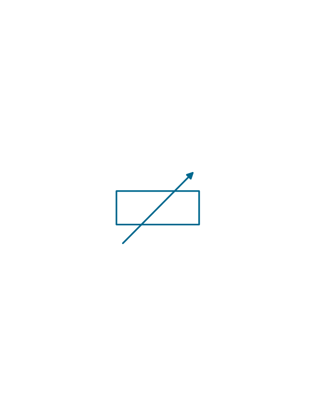
Variable attenuator
Attenuator
Electrical Symbols, Electrical Schematic Symbols

Circuits and Logic Diagram Software

Electrical Drawing Software and Electrical Symbols

Retract resistor check valve application: pneumatic cylinder, piston driven by Compressed air through 2 Retract resistor check valves.
"A check valve, clack valve, non-return valve or one-way valve is a valve that normally allows fluid (liquid or gas) to flow through it in only one direction.
Check valves are two-port valves, meaning they have two openings in the body, one for fluid to enter and the other for fluid to leave. There are various types of check valves used in a wide variety of applications. Check valves are often part of common household items. Although they are available in a wide range of sizes and costs, check valves generally are very small, simple, or inexpensive. Check valves work automatically and most are not controlled by a person or any external control; accordingly, most do not have any valve handle or stem. The bodies (external shells) of most check valves are made of plastic or metal.
An important concept in check valves is the cracking pressure which is the minimum upstream pressure at which the valve will operate. Typically the check valve is designed for and can therefore be specified for a specific cracking pressure.
Heart valves are essentially inlet and outlet check valves for the heart ventricles, since the ventricles act as pumps." [Check valve. Wikipedia]
This hydraulic schematic example was redrawn using ConceptDraw PRO diagramming and vector drawing software from the Wikimedia Commons file: Retract resistor check valve application.png.
[commons.wikimedia.org/ wiki/ File:Retract_ resistor_ check_ valve_ application.png]
The hydraulic engineering drawing example "Retract resistor check valve application" was created using the ConceptDraw PRO diagramming and vector drawing software extended with the Mechanical Engineering solution from the Engineering area of ConceptDraw Solution Park.
Hydraulic schematic

Swim Lane Flowchart Symbols

Electrical Symbols — Logic Gate Diagram

Process Flow Diagram

 Electrical Engineering
This solution extends ConceptDraw DIAGRAM.9.5 (or later) with electrical engineering samples, electrical schematic symbols, electrical diagram symbols, templates and libraries of design elements, to help you design electrical schematics, digital and analog
- Design elements - Resistors | Electrical Symbols, Electrical Diagram ...
- Electrical Symbols, Electrical Diagram Symbols | Electrical Symbols ...
- Diagram Of Resistors
- Electrical Symbols, Electrical Diagram Symbols | Electrical Symbols ...
- Schematic Diagram Of Fixed Resistor
- Electrical Symbols — Resistors | Electrical Symbols — Logic Gate ...
- Retract resistor check valve application | Mechanical Engineering ...
- Electrical Symbols — Resistors | Design elements - Resistors ...
- Design elements - Resistors | Electrical Drawing Software and ...
- Electrical Symbols — Resistors | Electrical Symbols, Electrical ...
- Design elements - Resistors | Resistors - Vector stencils library ...
- Electrical Symbols, Electrical Diagram Symbols | Electrical Drawing ...
- Retract resistor check valve application | Valve Nrv Pump Single ...
- Design elements - Resistors | Thermistor Symbol Schematic Diagram
- Design elements - Resistors | Block Diagram Creator | Electrical ...
- Circuit diagram - EL 34 schematics | Pentode Voltage Controlled ...
- Retract resistor check valve application | Process Flowchart ...
- Design elements - Resistors | Design elements - Electrical circuits ...
- Design elements - UML use case diagrams | Retract resistor check ...
- Electrical Symbols — Resistors | Electrical Symbols — Delay ...