HelpDesk
How to Create a Telecommunication Network Diagram in ConceptDraw PRO
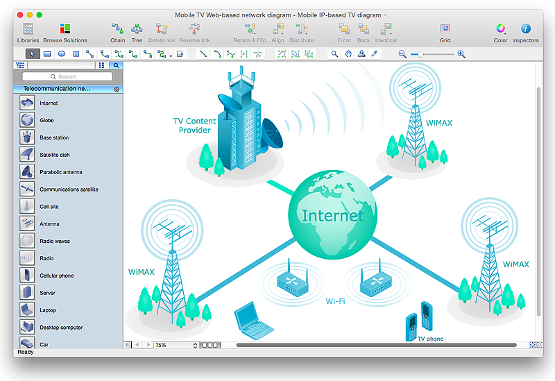
Telecommunication network diagram displays components and connections in a telecommunication network: how they are interacted between each other and with end-users. Telecommunication network diagrams usually created by system engineers for planning telecom networks. Also they may be useful for a network management. Telecom network diagram visualizes the level of security and user access to certain eqipment and data within a current network. Telecom network diagram can be used to identify weak points of an entire network or a part of it. ConceptDraw PRO allows you to draw a simple and clear Telecommunication Network diagrams.Network Diagram Software Logical Network Diagram
Perfect Network Diagramming Software with examples of LAN Diagrams. ConceptDraw Network Diagram is ideal for network engineers and network designers who need to draw Logical Network diagrams.
 Network Layout Floor Plans
Network Layout Floor Plans solution extends ConceptDraw PRO software functionality with powerful tools for quick and efficient documentation the network equipment and displaying its location on the professionally designed Network Layout Floor Plans. Never before creation of Network Layout Floor Plans, Network Communication Plans, Network Topologies Plans and Network Topology Maps was not so easy, convenient and fast as with predesigned templates, samples, examples and comprehensive set of vector design elements included to the Network Layout Floor Plans solution. All listed types of plans will be a good support for the future correct cabling and installation of network equipment.
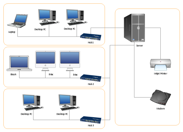
"Physical topology refers to the placement of the network's various components, including device location and cable installation...
The shape of the cabling layout used to link devices is called the physical topology of the network. This refers to the layout of cabling, the locations of nodes, and the interconnections between the nodes and the cabling. The physical topology of a network is determined by the capabilities of the network access devices and media, the level of control or fault tolerance desired, and the cost associated with cabling or telecommunications circuits." [Network topology. Wikipedia]
This physical LAN diagram example was created using the ConceptDraw PRO diagramming and vector drawing software extended with the Computer and Networks solution from the Computer and Networks area of ConceptDraw Solution Park.
Used Solutions
- Telecommunication Network Diagrams | Design elements ...
- Network Layout Floor Plans | ConceptDraw PRO Network Diagram ...
- Sample Communication Cable Diagram
- Active Directory Diagrams | Telecommunication Network Diagrams ...
- Network equipment and cabling layout - Template | Network layout ...
- Electrical Symbols, Electrical Diagram Symbols ...
- Layout Diagrams Cables
- Cable Network. Computer and Network Examples | Network ...
- Sketch Of A Layout Plan For Telephone Exchange
- Electrical and Telecom Plan Software | Telecommunication Network ...
- Network Layout Floor Plans | Network Diagram Software LAN ...
- Network Glossary Definition | Communication network diagram ...
- Network Layout Floor Plans | Design elements - Network layout ...
- Network Layout | Network Diagram Examples | Network Topologies ...
- Wire Layout Internet Cable
- Telecom Network Topology Diagram
- Communication network diagram
- Sample Floor Plan For Data Communication
- How To use Switches in Network Diagram | Computer network ...
- Basic Network Diagram | Network wiring cable . Computer and ...


