HelpDesk
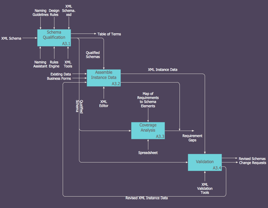
How to Create an IDEF0 Diagram for an Application Development
IDEF0 methods are intended to model the functions of a process, creating a graphical model that displays: what controls the function, who makes it, what resources are used and how they are connected with other functions. The IDEF0 tool is used to model the decisions, actions, and activities of a software system during the development process . IDEF0 diagram graphically depicts a model of a desired version of the application. ConceptDraw PRO allows you to create and communicate the IDEF0 diagrams of any complexity.- Online Diagram Tool | UML Component Diagram Example - Online ...
- UML Diagram Editor | Diagramming Software for UML Composite ...
- Online Diagram Tool | UML Component Diagram Example - Online ...
- Online Diagram Tool | UML Component Diagram Example - Online ...
- Timing Diagram Editor
- Diagram Editor Online
- Uml Diagram Editor Online
- Online Uml Diagram Editor
- Create Idef0 Diagrams Online
- Online Diagram Editor
- UML Diagram Editor | Diagramming Software for UML Composite ...
- Online Visio Editor Free
- UML Diagram Editor | UML Diagrams with ConceptDraw PRO | Data ...
- Online Microsoft Visio Editor
- Deployment Diagram For Online Bookstore In Uml
- Workflow Diagram Software Mac | ConceptDraw Solution Park ...
- State Diagram Example - Online Store | | UML State Machine ...
- Data Flow Diagrams | ConceptDraw PRO DFD Software | Gane ...
- How To Draw Data Flow Diagram
- Cross-Functional Flowchart (Swim Lanes) | Swim Lane Diagrams ...
