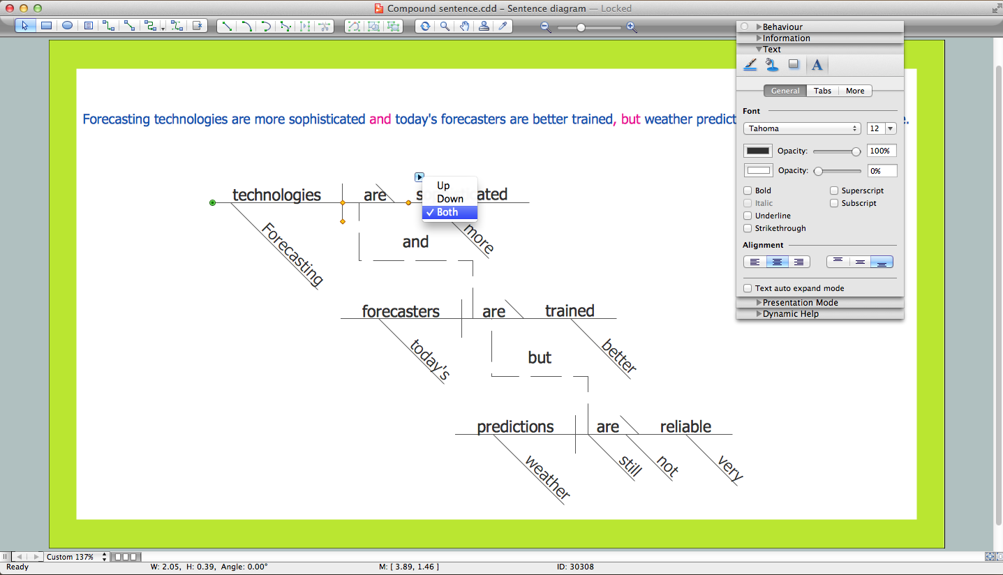
Sentence Diagrammer
Entity Relationship Diagram - ERD - Software for Design Crows Foot ER Diagrams
_Win_Mac.png)

HelpDesk
Event-driven Process Chain (EPC) Diagram Software
How To use House Electrical Plan Software


Entity Relationship Diagram Symbols

HelpDesk
How to Draw a Circular Arrows Diagram

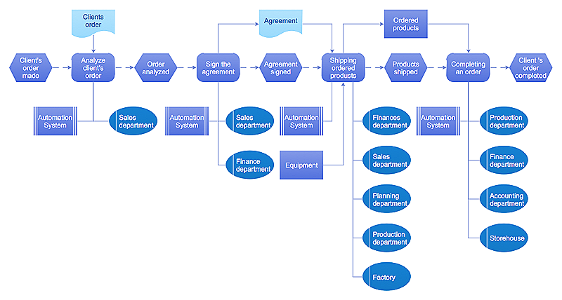
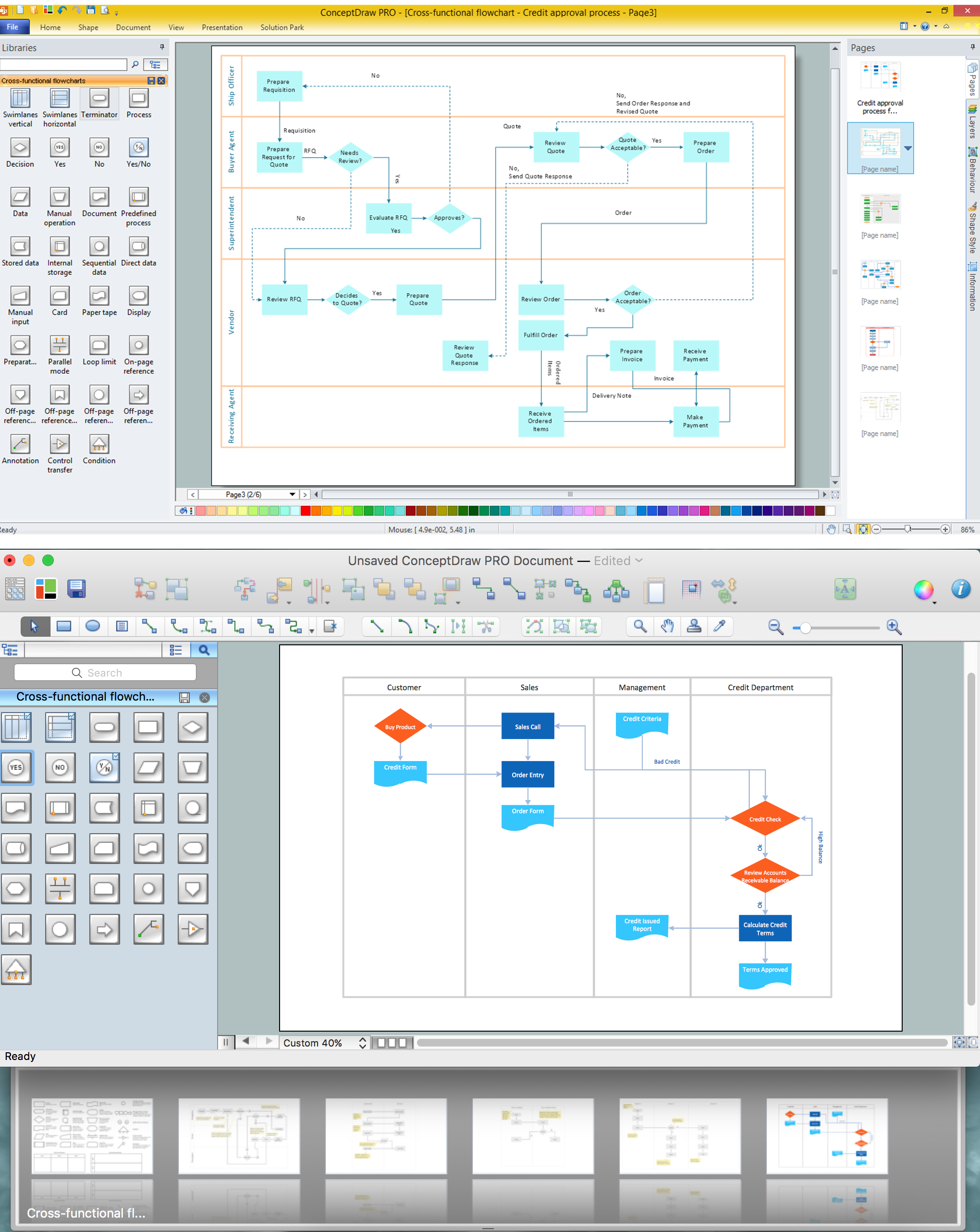
Cross-Functional Flowchart

How to Use the ″Online Store PR Campaign″ Sample

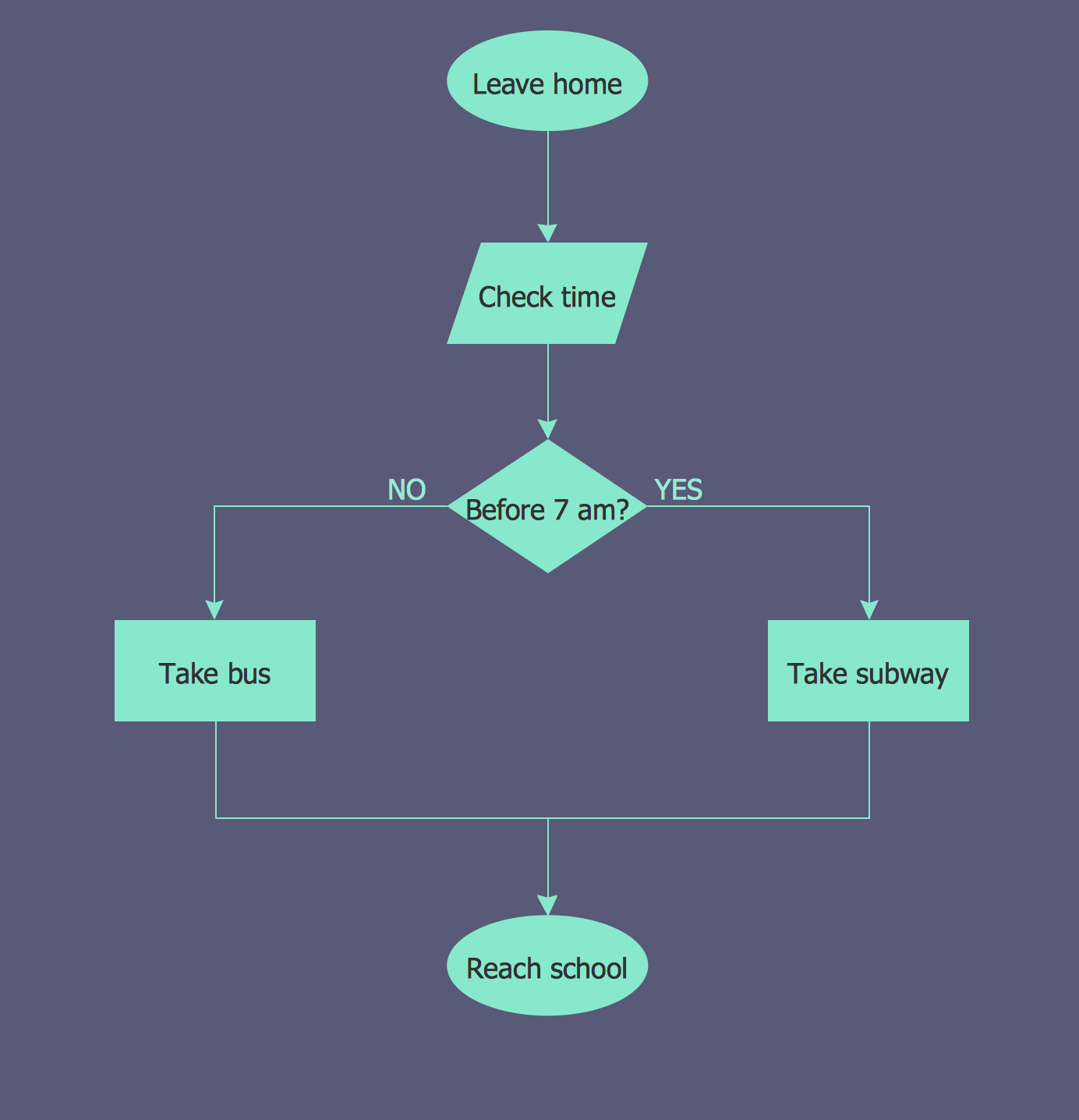
Flowchart Examples
ConceptDraw DIAGRAM DFD Software

- Diagramming Sentences Online Tool
- Online Sentence Diagramming Tool
- Free Online Sentence Diagramming Tool
- Free Sentence Diagrammer | Sentence Diagram | How to Diagram ...
- Free Sentence Diagrammer | Online Diagram Tool | Sentence ...
- Language Learning | Bio Flowchart | Network Diagram Examples ...
- Make Venn Diagram Online Free
- Free Sentence Diagrammer | Sentence Diagram | Local area ...
- Make A Venn Diagram Online For Free