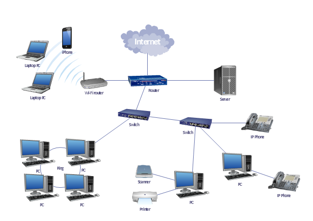
"A local area network (LAN) is a computer network that interconnects computers in a limited area such as a home, school, computer laboratory, or office building using network media. The defining characteristics of LANs, in contrast to wide area networks (WANs), include their smaller geographic area, and non-inclusion of leased telecommunication lines. Ethernet over twisted pair cabling, and Wi-Fi are the two most common technology standards currently used to build LANs." [Local area network. Wikipedia]
This local area network (LAN) topology diargam example was created using the ConceptDraw PRO diagramming and vector drawing software extended with the Computer and Networks solution from the Computer and Networks area of ConceptDraw Solution Park.
This local area network (LAN) topology diargam example was created using the ConceptDraw PRO diagramming and vector drawing software extended with the Computer and Networks solution from the Computer and Networks area of ConceptDraw Solution Park.
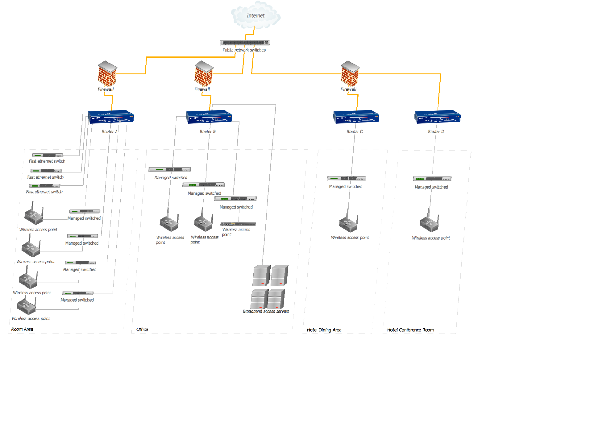
Hotel Network Topology Diagram. Hotel Guesthouse WiFi Network
The Computer and Networks solution from Computer and Networks area of ConceptDraw Solution Park provides examples, templates and vector stencils library with symbols of local area network (LAN) and wireless LAN (WLAN) equipment.Use it to draw the physical and logical network topology diagrams for wired and wireless computer communication networks.
"Logical topology, or signal topology, is the arrangement of devices on a computer network and how they communicate with one another. How devices are connected to the network through the actual cables that transmit data, or the physical structure of the network, is called the physical topology. Physical topology defines how the systems are physically connected. It represents the physical layout of the devices on the network. The logical topology defines how the systems communicate across the physical topologies.
Logical topologies are bound to network protocols and describe how data is moved across the network. ...
EXAMPLE : twisted pair Ethernet is a logical bus topology in a physical star topology layout. while IBM's token ring is a logical ring topology, it is physically set up in star topology." [Logical topology. Wikipedia]
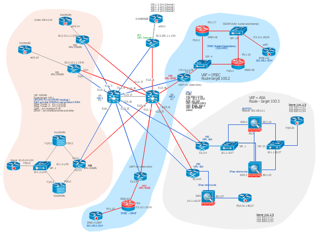
This Cisco logical computer network diagram example was created using the ConceptDraw PRO diagramming and vector drawing software extended with the Cisco Network Diagrams solution from the Computer and Networks area of ConceptDraw Solution Park.
This Cisco network diagram example was drawn on the base of the figure illustrating the post "Cisco Lab 1 : Network Design from the requirement" from the blog "Thai Cisco Club".
"1. Core service porvider by assign P router as P1 and P2, PE router as PE1 - 8 for support CE router of customers.
2. From 1st customer project, assign R1-DMVPN and R2-DWVPN as DMVPN Hub, and R3-DMVPN and R4-DMVPN as DMVPN-Spoke that on different site.
3. From 2nd customer project, assign IP-SEC R1 and IP-SEC R2 as SSO-IP-SEC Router on HQ site, and IP-SEC R3 as branch site that far away."
[thai-cisco-club.blogspot.com/ 2011/ 10/ cisco-lab-1-network-design-from.html]
The diagram example "Cisco network design from the requirement" was created using the ConceptDraw PRO diagramming and vector drawing software extended with the Cisco Network Diagrams solution from the Computer and Networks area of ConceptDraw Solution Park.
- Wireless router network diagram | Network Diagram Software Home ...
- Wireless router network diagram | What Is a Wireless Network ...
- Network Diagram Software Home Area Network | Network Gateway ...
- Wireless router network diagram
- Cisco Routers. Cisco icons, shapes, stencils and symbols | Wireless ...
- Network Gateway Router | Wireless router network diagram | Cisco ...
- Network Gateway Router | Wireless router network diagram | Cisco ...
- Wireless router network diagram | Network Diagram Software Home ...
- Network Gateway Router | Computer network diagram template ...
- Network Gateway Router | Wireless router network diagram ...
- Network Gateway Router | Wireless router network diagram | How ...
- Network Gateway Router | Cisco Routers. Cisco icons, shapes ...
- Network Gateway Router | Design elements - Wireless networks ...
- Network Gateway Router | Cisco Intelligent Services Gateway ...
- Network Gateway Router | Network Printer | Network Hubs | Ethernet ...
- Communication network diagram | Computers and Communications ...
- Logical network diagram | Diagramming tool - Amazon Web ...
- Hotel Network Topology Diagram . Hotel Guesthouse WiFi Network ...
- Network Gateway Router | Hotel Network Topology Diagram | How ...
- Long-range Wi-Fi network diagram | Wireless networks - Vector ...


