HelpDesk
How to Create an IDEF0 Diagram for an Application Development
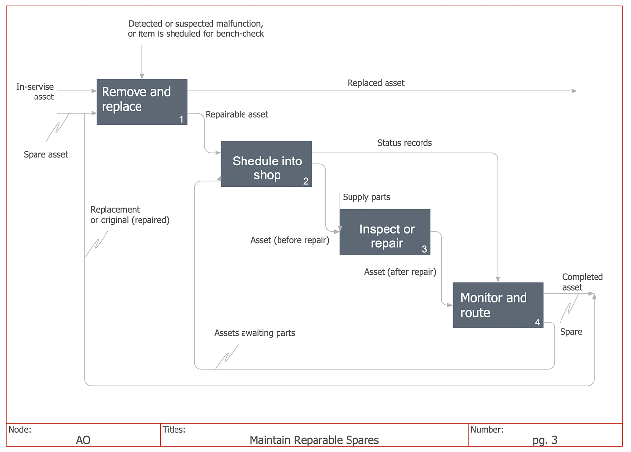
IDEF0 methods are intended to model the functions of a process, creating a graphical model that displays: what controls the function, who makes it, what resources are used and how they are connected with other functions. The IDEF0 tool is used to model the decisions, actions, and activities of a software system during the development process. IDEF0 diagram graphically depicts a model of a desired version of the application. ConceptDraw DIAGRAM allows you to create and communicate the IDEF0 diagrams of any complexity.- Universal Diagramming Area | Physics Diagram Maker Software
- Workflow Diagram Software Mac | Create Flow Chart on Mac ...
- Universal Diagramming Area | SDL Diagram | IDEF0 standard with ...
- Block Diagram Creator
- Architectural Bubble Diagram Maker
- Block Diagram | Process Flowchart | Engineering | Draw Block ...
- Memory Object Diagram | Program Structure Diagram | ORM ...
- How To Create a Bubble Chart | ER diagram tool for OS X | Workflow ...
- Procedure For Matrix Flow Diagramm In Tqm
- Diagramm Software
- Analysis Diagram Examples
- How to Create Flowcharts for an Accounting Information System ...
- How to Create an IDEF0 Diagram for an Application Development ...
- Decision Making | Block diagram - Customer decision making ...
- Physics Diagram Maker
- ER diagram tool for OS X | Business Productivity Diagramming ...
- Modelling Concepts for Business Engineering - EPC | ConceptDraw ...
- Fishbone Diagram | Entity-Relationship Diagram (ERD ...
- UML 2 4 Process Flow Diagram | Software Work Flow Process in ...
- Venn Diagrams | Venn Diagram | How to Create a Venn Diagram in ...
