"An air-operated valve is a type of power operated valve that uses air pressure against a piston or diaphragm to produce linear or circular movement to operate a valve. Types are 2-way, 3-way and 4-way. The 2 way air-operated valves can be either normally closed or normally opened." [Air-operated valve. Wikipedia]
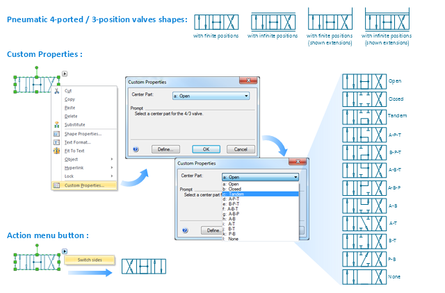
The Windows template "Pneumatic 4-ported 3-position valve" for the ConceptDraw PRO diagramming and vector drawing software is included in the Mechanical Engineering solution from the Engineering area of ConceptDraw Solution Park.
www.conceptdraw.com/ solution-park/ engineering-mechanical
The Windows template "Pneumatic 4-ported 3-position valve" for the ConceptDraw PRO diagramming and vector drawing software is included in the Mechanical Engineering solution from the Engineering area of ConceptDraw Solution Park.
www.conceptdraw.com/ solution-park/ engineering-mechanical
"A piping and instrumentation diagram/ drawing (P&ID) is a diagram in the process industry which shows the piping of the process flow together with the installed equipment and instrumentation. ...
P&IDs play a significant role in the maintenance and modification of the process that it describes. It is critical to demonstrate the physical sequence of equipment and systems, as well as how these systems connect. During the design stage, the diagram also provides the basis for the development of system control schemes, allowing for further safety and operational investigations, such as a Hazard Analysis and Operability Study...
For processing facilities, it is a pictorial representation of:
Key piping and instrument details,
Control and shutdown schemes,
Safety and regulatory requirements,
Basic start up and operational information." [Piping and instrumentation diagram. Wikipedia]
The piping and instrumentation diagram template for the ConceptDraw PRO diagramming and vector drawing software is included in the Chemical and Process Engineering solution from the Engineering area of ConceptDraw Solution Park.
- Safety Valve P Id Symbol
- Mechanical Drawing Symbols | Pneumatic 5-ported 3-position valve ...
- Gate Valve Symbol Drawings
- Gate Valve Symbol
- Valve Diagram Symbols
- Valve Drawing Software
- Valves Line Diagrams
- Sign Of Gate Valve In Engineering Drawing
- Bearings - Vector stencils library | Mechanical Drawing Symbols ...
- ConceptDraw Arrows10 Technology | Piping and Instrumentation ...
- Symbol Of Valves In Drawing
- Time and clock pictograms - Vector stencils library | Road signs ...
- Interior Design Piping Plan - Design Elements | Design elements ...
- Pump P
- Pneumatic 5-ported 3-position valve template - Mac
- What Is P Id
- Symbol In P
- Mechanical Drawing Symbols | Pneumatic 5-ported 3-position valve ...
- Crude oil distillation unit - PFD | Jet fuel mercaptan oxidation treating ...
- Piping and instrumentation diagram template

-piping-and-instrumentation-diagram-template.png--diagram-flowchart-example.png)