Basic Flowchart Symbols and Meaning


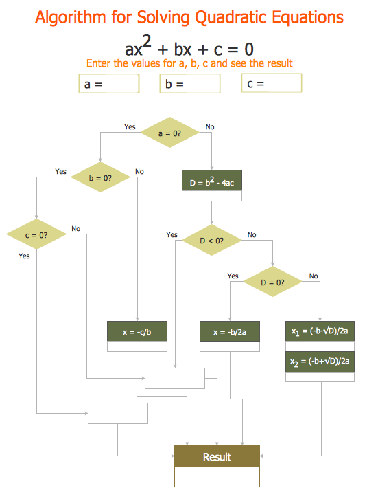
Mathematical Diagrams
ER Diagram Styles

Mathematics Symbols

ERD Symbols and Meanings


Types of Flowcharts


 Mathematics
Mathematics solution extends ConceptDraw DIAGRAM software with templates, samples and libraries of vector stencils for drawing the mathematical illustrations, diagrams and charts.
This engineering drawing shows different types of geometry of butt welds.
"Welds can be geometrically prepared in many different ways. The five basic types of weld joints are the butt joint, lap joint, corner joint, edge joint, and T-joint (a variant of this last is the cruciform joint). Other variations exist as well - for example, double-V preparation joints are characterized by the two pieces of material each tapering to a single center point at one-half their height. Single-U and double-U preparation joints are also fairly common - instead of having straight edges like the single-V and double-V preparation joints, they are curved, forming the shape of a U. Lap joints are also commonly more than two pieces thick - depending on the process used and the thickness of the material, many pieces can be welded together in a lap joint geometry." [Welding. Wikipedia]
This engineering drawing example was redesigned using the ConceptDraw PRO diagramming and vector drawing software from the Wikimedia Commons file: Butt Weld Geometry.GIF.
[commons.wikimedia.org/ wiki/ File:Butt_ Weld_ Geometry.GIF]
The engineering drawing example "Butt weld geometry" is included in the Mechanical Engineering solution from the Engineering area of ConceptDraw Solution Park.
Welding joint diagram

Mechanical Drawing Symbols

Chen ERD Diagram

- Draw Different Types Of Geometrical Shapes
- How to Draw Geometric Shapes in ConceptDraw PRO ...
- Different Types Of Geometry Diagram
- Mathematical Diagrams | How to Draw Geometric Shapes in ...
- Explain Different Geometrical Figures Used In Flowchart
- Network Layout Floor Plans | Draw Five Types Of Shapes
- Geometric Figures Of Kinds Of Solid
- How to Draw Geometric Shapes in ConceptDraw PRO | How to ...
- Types Of Shapes In Geometry
- How to Draw Geometric Shapes in ConceptDraw PRO | Basic ...