 Active Directory Diagrams
Active Directory Diagrams solution significantly extends the capabilities of ConceptDraw DIAGRAM software with special Active Directory samples, convenient template and libraries of Active Directory vector stencils, common icons of sites and services, icons of LDPA elements, which were developed to help you in planning and modelling network structures and network topologies, in designing excellently looking Active Directory diagrams, Active Directory Structure diagrams, and Active Directory Services diagram, which are perfect way to visualize detailed structures of Microsoft Windows networks, Active Directory Domain topology, Active Directory Site topology, Organizational Units (OU), and Exchange Server organization.
Active Directory Diagram

Active Directory Network. Computer and Network Examples

Active Directory
Active Directory Domain

"Microsoft Windows 2000 Server introduces Active Directory to replace domain functionality. Active Directory will continue to get the job done, but in a much more efficient way. Active Directory can be replicated between multiple domain controllers, so no single system is critical. In this way, the crucial data stored within Active Directory is both redundant and load-balanced.
A directory, in the most generic sense, is a comprehensive listing of objects. A phone book is a type of directory that stores information about people, businesses, and government organizations. Phone books typically record names, addresses, and phone numbers. Active Directory is similar to a phone book in several ways, and it is far more flexible. Active Directory will store information about organizations, sites, systems, users, shares, and just about any other network object that you can imagine. Not all objects are as similar to each other as those stored in the phone book, so Active Directory includes the ability to record different types of information about different objects." [technet.microsoft.com/ en-us/ library/ bb742424.aspx]
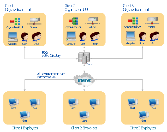
The AD diagram example "Active Directory structure diagram" was created using the ConceptDraw PRO diagramming and vector drawing software extended with the Active Directory Diagrams solution from the Computer and Networks area of ConceptDraw Solution Park.
A directory, in the most generic sense, is a comprehensive listing of objects. A phone book is a type of directory that stores information about people, businesses, and government organizations. Phone books typically record names, addresses, and phone numbers. Active Directory is similar to a phone book in several ways, and it is far more flexible. Active Directory will store information about organizations, sites, systems, users, shares, and just about any other network object that you can imagine. Not all objects are as similar to each other as those stored in the phone book, so Active Directory includes the ability to record different types of information about different objects." [technet.microsoft.com/ en-us/ library/ bb742424.aspx]
The AD diagram example "Active Directory structure diagram" was created using the ConceptDraw PRO diagramming and vector drawing software extended with the Active Directory Diagrams solution from the Computer and Networks area of ConceptDraw Solution Park.
Active Directory network diagram
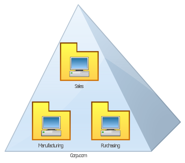
This AD diagram example was redesigned from the picture "Single root domain with a structured OU model" from the book "Active Directory for Dummies".
"A domain is the cornerstone that you lay whenever you create trees and forests. Regardless of whether you design a tree or a forest, the starting point is always the root domain. The root domain is the first domain that you create in your AD structure, and it sits at the top of your diagram.
The root domain of your tree, similar to any other domain, is a grouping of
resources built on the following components:
(1) Domain controllers.
(2) Security policies. ...
For many small and medium-sized companies, a single root domain with a
structured OU (organizational unit) model... provides sufficient flexibility for an AD tree. ...
However, larger companies, companies with complex organization charts, and
companies with multiple sites often find that a single domain isn’t suitable." [Steve Clines and Marcia Loughry, Active Directory® For Dummies®, 2nd Edition. 2008]
The Active Directory diagram example "Single root domain with a structured OU model" was created using the ConceptDraw PRO diagramming and vector drawing software extended with the Active Directory Diagrams solution from the Computer and Networks area of ConceptDraw Solution Park.
Active Directory network diagram
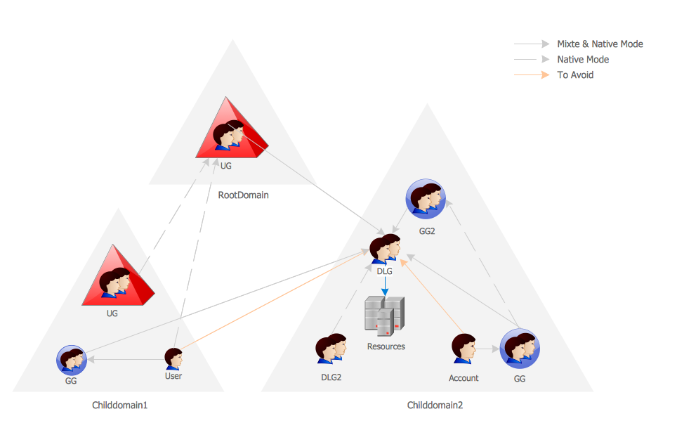
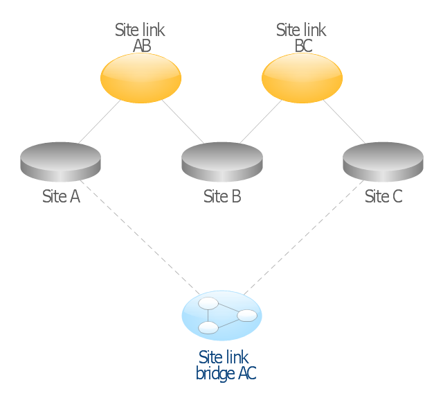
This AD diagram example was redesigned from the picture "Site links" from the book "Active Directory for Dummies".
"Site links represent the Active Directory replication paths between sites.
These paths are manually defined so that the designer has control over which network links the replication traffic occurs on. These site links also control how clients are directed to domain controllers when there’s no DC in the client’s local site. Each site link has the following attributes:
(1) Connected sites: A site link is defined by the sites to which it connects. A site link can connect two or more sites together.
(2) Network transport: Site links support replication communication over IP-based RPCs or with the Simple Mail Transport Protocol (SMTP). You normally want to use RPC whenever possible, but you can use SMTP when the sites you’re linking don’t support RPC.
(3) Cost: Each site link has a cost associated with it. Costs are used to assign preferences to links that determine which link should be followed when multiple link paths are available between sites. The cost represents what it “costs” to use this site link relative to the other site links and affects replication traffic as well as how users are assigned a domain controller. Links with lower cost values have preference over links with higher cost values. Cost values range from 1–32,767; the default being 100.
(4) Frequency: The frequency value defines how often a replication occurs
when using this site link (the replication latency). You can configure the time between replications from a minimum of 15 minutes to a maximum of 10,080 minutes (one week). The default frequency is 180 minutes.
(5) Schedule: The schedule dictates when this link is active and available for replication between the sites. The schedule can also control which days of the week the link is available. Normally, the schedule is set so that the link is available 24 hours a day, but you can set up different schedules on a per-day-of-the-week basis.
By creating a site link, you enable two or more sites to be connected and to share the same site link attributes (transport, cost, frequency, and schedule). By default, site links create transitive connectivity between sites.
If you create a site link between sites A and B and another site link between
sites B and C, an automatic connection (known as a site link bridge) is created between sites A and C..." [Steve Clines and Marcia Loughry, Active Directory® For Dummies®, 2nd Edition. 2008]
The Active Directory diagram example "Site links" was created using the ConceptDraw PRO diagramming and vector drawing software extended with the Active Directory Diagrams solution from the Computer and Networks area of ConceptDraw Solution Park.
Active Directory network diagram
Network diagrams with ConceptDraw DIAGRAM

 Computer Network Diagrams
Computer Network Diagrams solution extends ConceptDraw DIAGRAM software with samples, templates and libraries of vector icons and objects of computer network devices and network components to help you create professional-looking Computer Network Diagrams, to plan simple home networks and complex computer network configurations for large buildings, to represent their schemes in a comprehensible graphical view, to document computer networks configurations, to depict the interactions between network's components, the used protocols and topologies, to represent physical and logical network structures, to compare visually different topologies and to depict their combinations, to represent in details the network structure with help of schemes, to study and analyze the network configurations, to communicate effectively to engineers, stakeholders and end-users, to track network working and troubleshoot, if necessary.
- Active Directory Domain Services | Network Diagram Examples ...
- Tree and Forest (Full Trust) - Active Directory network diagram ...
- Domain Controller Diagram
- Active Directory Diagrams | Domain Controller And Forest Structure ...
- Domain Structure Example Diagram
- Software Defined Networking System Overview | Cisco Network ...
- Network Diagram Examples | Active Directory Domain Services ...
- Active Directory Diagram | Active Directory Domain Services ...
- Design Element: Active Directory for Network Diagrams | Network ...
- Active Directory Diagrams | Design Element: Active Directory for ...