Data Modeling Diagram

Model Based Systems Engineering

Data Flow Diagram

UML Class Diagram Generalization Example UML Diagrams

UML 2 4 Process Flow Diagram

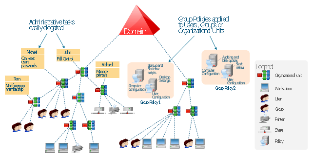
 Active Directory Diagrams
Active Directory Diagrams solution significantly extends the capabilities of ConceptDraw DIAGRAM software with special Active Directory samples, convenient template and libraries of Active Directory vector stencils, common icons of sites and services, icons of LDPA elements, which were developed to help you in planning and modelling network structures and network topologies, in designing excellently looking Active Directory diagrams, Active Directory Structure diagrams, and Active Directory Services diagram, which are perfect way to visualize detailed structures of Microsoft Windows networks, Active Directory Domain topology, Active Directory Site topology, Organizational Units (OU), and Exchange Server organization.
Local area network (LAN). Computer and Network Examples
 diagram")

UML Use Case Diagram Example - Estate Agency

Design Element: Crows Foot for Entity Relationship Diagram - ERD

Database Design

Design Data Flow. DFD Library

 EXPRESS-G data Modeling Diagram
EXPRESS-G data Modeling Diagram solution extends the ConceptDraw DIAGRAM software functionality with capabilities of EXPRESS data modeling language, includes powerful data modeling tools, Express-G diagram tool, database diagram tool, database design tool, wide variety of pre-made vector objects of EXPRESS-G notation and EXPRESS-G diagrams samples allowing software developers, software designers, software engineers and other stakeholders to make their data models for information systems, to develop the databases, to learn the principles of construction EXPRESS-G diagrams and helping to draw their own EXPRESS-G Data Modeling Diagrams, Express-G Diagrams or Database Model Diagram without any efforts.
Active Directory Domain

 Enterprise Architecture Diagrams
Enterprise Architecture Diagrams solution extends ConceptDraw DIAGRAM software with templates, samples and library of vector stencils for drawing the diagrams of enterprise architecture models.
HelpDesk
How to Create an Active Directory Diagram

 Object-Role Modeling (ORM) Diagrams
Object-role Modeling (ORM) Diagram solution with powerful vector diagramming and data modeling tools, large quantity of specially developed samples and examples, and rich variety of vector objects corresponding to common ORM notation, ideally suits for developing the comprehensive, clear and visual Object-role Modeling (ORM) diagrams and schematics, understandable for all interested people from the different fields and business directions, for designing the ORM models, and demonstrating advantages from the use of ORM and its notation. It is intended for software developers and computer engineers, specialists in a field of Object-oriented programming (OOP), database architects, web-application constructors and developers, etc.
This example was drawn on the base of the Figure 2 illustrating the "Active Directory FAQ" from the website "Information Management Systems & Services" (IMSS) of the California Institute of Technology (Caltech) campus. [imss.caltech.edu/ node/ 412]
"By using the Active Directory® Domain Services (AD DS) server role, you can create a scalable, secure, and manageable infrastructure for user and resource management, and you can provide support for directory-enabled applications, such as Microsoft® Exchange Server. ...
AD DS provides a distributed database that stores and manages information about network resources and application-specific data from directory-enabled applications. Administrators can use AD DS to organize elements of a network, such as users, computers, and other devices, into a hierarchical containment structure. The hierarchical containment structure includes the Active Directory forest, domains in the forest, and organizational units (OUs) in each domain. A server that is running AD DS is called a domain controller." [technet.microsoft.com/ en-us/ library/ 9a5cba91-7153-4265-adda-c70df2321982]
The Active Directory Domain Services diagram example was created using the ConceptDraw PRO diagramming and vector drawing software extended with the Active Directory Diagrams solution from the Computer and Networks area of ConceptDraw Solution Park.
Active Directory hierarchical structure
Scrum

Active Directory Network. Computer and Network Examples

Cisco Routers. Cisco icons, shapes, stencils and symbols

- Domain Model Diagram For Library Management System
- Domain Diagram For Transport Management System
- Waterfall Model For Library Management System Ppt
- Er Diadram For Online Library Management System
- Er Diagram For Library Management System Pdf Ppt
- Ternary Relation In Er Diagram Library Management System
- Class Diagram For Library Management System Ppt
- System Architecture Diagram For Library Management
- UML Class Diagram Example for GoodsTransportation System ...
- UML Class Diagram Generalization Example UML Diagrams
- Class Diagram For Library Management System Pdf
- Class Diagram For Library Managenment In Software Engineering Ppt
- Network Diagram Examples | IDEF9 Standard | Network ...
- Library Management System Which Topology And Protocols Used
- Uml Diagrams For Library Management System Doc
- Smart Draw Uml Library Management With Instances
- Data Flow Diagram Symbols. DFD Library | DFD Library System ...
- Entity Relationship Diagram Symbols | Martin ERD Diagram | Entity ...
- Draw The Context Level Diagram Of Library Management System